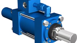
Cylinder Sizing Considerations for Precision System Control
Despite careful design and implementation of sophisticated control electronics, fluid power system performance can be degraded by incorrect sizing or physical location of system components. A common design oversight is the use of undersized cylinders. In an attempt to increase actuator speed, designers may specify small bore cylinders, based on the assumption that for a given amount of oil flow, a smaller cylinder will produce higher velocities. However, this assumption only holds for very light loads.
For cylinders moving moderate to heavy masses, the acceleration, velocity, and deceleration are limited by the available force, rather than oil flow. Because cylinder bore determines the force an actuator can produce, if the cylinder diameter is too small, the actuator may not be capable of attaining the desired speeds or required cycle times needed for the application.
The Temptation of Simplified Formulas
Pressure of design, market, and time constraints, can make it tempting to use simplified, first-order approximations to govern system design. And this approach might achieve acceptable results for simple machines. As control systems become more sophisticated, and increased importance is placed on efficiency and economy, reliance on these design approximations tends to result in overly conservative designs. The cost of this approach can be measured in larger, more expensive cylinders, valves, and pumps. Consequently, a supplier or distributor may lose a bid to a competitor due to extra cost.
A formula such as V =Q / A is a starting point. However, this formula is true only when the mass is zero. Since most real-world systems need to move a mass of some kind, this formula should only be used in the alternate form, Q = V ´ A, when calculating system flow using velocity and area.
Force Makes It Go
The following “rule of thumb” formula takes into account that force is needed to produce acceleration, and servovalves require pressure drop for control (servovalves are typically rated at 70 bar, approximately equal to 1,000 psi).
A = L / (P – 1,000psi)
Where:
A = area(in.2)
L = peak load (lb)
P = system pressure (psi)
This formula assumes that peak load occurs at peak speed. The peak load must include the force necessary to accelerate or decelerate the load, friction, and the load’s weight if the system is vertical. Minimum system pressure should be used. This formula should be applied to both extend and retract directions, but it neglects the opposing force required to push oil out of the cylinder’s return side. Therefore, the resulting estimated size should be considered a minimum.
For high-performance motion, the system’s natural frequency should typically be at least three to four times higher than the frequency of acceleration of the motion profile. Since the cylinder’s natural frequency is a function of area, a second check of the necessary cylinder area can be made using the following formula for calculating natural frequency:
Where:
ωn is the natural frequency of the cylinder and load (Hz)
β is the bulk modulus of oil (lb/in.2)
A is the average area of the piston (in.2)
V is the total volume of oil trapped between the valve and the piston (in.3)
M is the mass of the load (lb)
We can rearrange this formula, with modifications to include vertical weight, to determine what the area should be for a desired natural frequency. For example, if the frequency of acceleration of the motion profile is 5 Hz, then the system’s natural frequency should be near the 15- to 20-Hz range. The formula will produce a desired cylinder area for this frequency of motion.
A = (ƒ´4)2 ´ π2 ´ l ´ (M/g´ß)
Where:
A = average cylinder area (in.2)
ƒ = frequency of acceleration of motion (Hz)
l = length (in.)
M = load mass (lb.)
g = acceleration due to gravity (32ft/sec2)
ß = bulk modulus (incompressibility constant) of the oil (~200,000 lb/in.2)
This formula tends to underestimate the correct cylinder diameter by making some optimistic assumptions. The most significant is that the valve is sitting right on the cylinder. If this isn’t the case, the cylinder length should be increased. The diameter of the hose is not as large as the cylinder, but hose is much more expansive than the cylinder. Hose or extra pipe between the valve and the cylinder complicates these calculations by adding extra oil volume to the system. This extra volume must be accounted for or the system will not perform as expected.
Increasing the diameter of the cylinder increases the natural frequency (stiffness) of the system, allowing the control system to manage faster accelerations and decelerations. This results in higher system performance when properly tuned. However, larger cylinders require larger valves and more oil. Excessively large cylinders increase cost and, because large valves tend to be slower, at some point increasing valve size will no longer increase system response. Therefore, a careful compromise must be found.
An accurate estimation of performance taking into account different system variables can be obtained by calculating Jack L. Johnson’s VCCM formula. This formula can be found in the following reference books by Johnson: Designers Handbook for Electro Hydraulic Servo and Proportional Systems and Basic Electronics for Hydraulic Motion Control.
Both Johnson and Delta Computer Systems’ Peter Nachtwey have published refinements to the VCCM equation that account for extra oil volume. Click here for more information. This analysis requires mathematical system simulation, but produces an accurate forecast of the performance before a system is constructed; it provides additional confidence in the design decisions.
Striking a Balance
As mentioned earlier, best control is realized if the system’s natural frequency is approximately three to four times the maximum required frequency of acceleration. Most modern control systems with proportional and integral (PI) control, and both velocity and acceleration feedforwards can control a system within acceptable tolerances. Feedforwards predict the required control output, rather than waiting for an error between the requested and actual control signals. However, using motion controllers, such as the Delta Computer System’s RMC family, allows the designer to specify components that produce accelerations that are much closer to the system’s natural frequency. This ability comes, in part, from the RMC’s algorithms that go beyond PID gains, velocity, and acceleration feedforwards.
With advanced motion control, we can achieve small following errors with the ratio of system natural frequency to frequency of acceleration of about 2 to 2.5, as long as the system does not exhibit significant stick-slip characteristics. Consequently, this provides freedom to deal with real-world design constraints while still achieving excellent machine performance.
Optimizing cylinder sizing and using a sophisticated motion control system can result in lower total system cost. This is due to having right-sized cylinders, valves, and pumps that are matched for the task at hand. An added benefit is a machine with lower operational costs. In many cases, the cost savings of right-sized equipment can more than offset the price of a high-performance motion controller, one which also provides easy setup, programming, tuning, and diagnostics. A small amount of design effort initially can yield large dividends later.
Aaron Heinrich is motion products marketing manager at Delta Computer Systems Inc., Battle Ground, Wash.


