Download this article in .PDF format
This file type includes high resolution graphics and schematics when applicable.
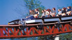
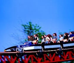
Most roller coasters rely on fear-inducing heights and speed from gravity to excite riders. Top Thrill Dragster, at Cedar Point, Sandusky, Ohio, is no exception. However, instead of relying on a chain or cable to laboriously pull the coaster up its first hill -— in this case, a 420-ft hill — Top Thrill Dragster relies on kinetic energy to propel coasters up its hill in mere seconds.
Top Thrill Dragster accelerates coaster trains from zero to 120 mph in about 4 sec. At that speed, coasters have just enough kinetic energy to scale that monstrous hill. From there, gravity pulls the coaster down the other side of the hill, where the coaster once again reaches speeds of about 120 mph.
The biggest challenge to this application was finding a technology that could accelerate a 12,000-lb coaster train — plus the weight of 18 passengers — to 120 mph in 4 sec. Cedar Point's Monty Jasper, vice president, maintenance, reveals that ride designers initially considered the latest coaster technology — linear induction motors — to accelerate Top Thrill Dragster coasters.
"Linear motors would have been energy efficient and required little maintenance, but they wouldn't have been able to accelerate Top Thrill Dragster to 120 mph in four seconds," explains Jasper. "They would have required a longer approach to the hill, and had we gone that route, we would've had to remove or relocate two nearby attractions. Plus, riders would have been denied the excitement of such high acceleration."
Energy rollback
An important aspect of the launch system is that coaster trains accelerate to a speed that allows them to just barely scale the hill. Jasper continues, "When the coaster reaches the top of the hill, ideally, it will have just enough momentum to roll beyond the highest portion of the hill. From there, gravity takes over and pulls the coaster down the other side of the hill."
A ride computer regulates the amount of energy transmitted for each launch. In addition to operator inputs, the computer also receives signals from switches and sensors throughout the attraction. For example, a pair of inductive sensors mounted near the top of the hill detect when a coaster passes by. Because the sensors are spaced a known distance apart, the computer can calculate velocity by measuring the time interval between each sensor activation. If calculations indicate a coaster has gone too slow or too fast, the computer commands the launch system to increase or decrease speed of the next launch.
Jasper explains, "The computer actually evaluates speed of the last three coasters and calculates an average. This determines speed of the next coaster. So if three consecutive coasters are filled with lightweight passengers, then a bunch of football players fill the next one, that fourth coaster probably won't have enough momentum to make it up and over the hill."
When a coaster train doesn't have enough energy to conquer the hill, it rolls back toward the launch station. Jasper explains, "If a conventional coaster doesn't make it up the first hill, it's because of a malfunction. Plus, mechanical catches are always in place to keep conventional coasters from rolling back. This would allow evacuating the coaster — an extremely unlikely event.
"But Top Thrill Dragster is not a conventional coaster. It goes virtually straight up and straight down. So we don't want to stop the coaster somewhere up that 420-ft hill to evacuate passengers. The simple solution, then, is to let the coaster roll back. It is not a malfunction, and we let guests know ahead of time that a coaster could roll back."
When a coaster occasionally does roll back, it doesn't come charging into the loading area at 120 mph. Instead, a permanent magnet braking system automatically decelerates the train if it should roll back. Each car contains copper fins that fit between slots of a series of permanent magnets situated along the length of track between the launch station and hill. When a coaster is ready for launch, pneumatic cylinders move the permanent magnets out of the way so the coaster can pass. But once a coaster passes, the magnets move back into place so they can stop a coaster if it rolls back.
Because the braking system uses permanent magnets, coasters will be stopped even if a power failure occurs after a coaster is launched. Plus, they are actuated pneumatically in a fail-safe arrangement that requires an electrical signal to move the magnets out of the way for launching. So if power fails, the brakes will automatically be positioned to stop a coaster. A similar permanent magnet braking system is used to decelerate coasters after they have descended the far side of the hill. Position of these brakes, however, is fixed.
How hydraulics does it
So how do you accelerate a 15,000-lb loaded coaster train from zero to 120 mph in only 4 seconds? With hydraulics, of course. Jasper says the hydraulic launch system transmits up to about 10,000 hp to accelerate a coaster to about 120 mph. This power is needed for only a few seconds, which is a big reason why hydraulics was chosen: its inherent ability to store energy and release it rapidly with controlled acceleration and velocity.
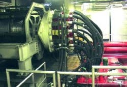
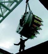
The launch system uses two identical hydraulic systems. Each culminates in 16 hydraulic motors that drive an internal ring gear. The pair of ring gears drives a dual-input planetary gearbox, which, in turn, drives a sheave that pulls a cable to launch a coaster.
Fluid to the motors flows through a 2-in. 6-wire hose, and 6-in. hose is used for return flow to minimize pressure drop. Each motor is supplied by its own pump, so the launch system consists of 32 pumps and 32 motors. (An auxiliary hydraulic drive provides power to pull the cable back to the loading area, where it engages the next coaster.)
System operating pressure is 320 bar ( 4640 psi), and peak power is 10,000 hp. So a simple calculation reveals that total flow to the motors reaches about 3650 gpm. Even with 32 pumps, the system would require each pump to deliver more than 100 gpm. Such is not the case. Instead, each pump-motor combination relies on a piston-type accumulator and gas pressure vessels (called gas bottles) to supply the majority of flow for 4-sec launch interval. A piston inside each accumulator separates its wet side from its dry side. The wet side is piped into the hydraulic system and filled with hydraulic fluid. The dry side contains pressurized nitrogen and is plumbed to the gas bottles, which are also filled with compressed nitrogen.
Before a launch occurs, each of the 32 pumps forces oil into the wet side of its respective accumulator. The additional volume of oil pushes on the piston and forces nitrogen out of the dry side and into the gas bottles. Because volume of the gas bottles is fixed, pressure of the nitrogen increases.
In less than a minute the gas bottles have achieved a full pressure charge, so the system can shift to a standby mode. When the launch sequence begins, an electrical signal opens a two-way valve, routing pressurized fluid from the wet side of the accumulator to the respective hydraulic motor. This surge of fluid combines with flow from the respective pump to drive the motor.
Using accumulators to supplement pump flow is common in hydraulics. But rarely is it used to give people the ride of a lifetime.
Hydraulic restraint makes safety first
Riding Top Thrill Dragster, or any thrill ride that reaches high elevations and high speeds, can be a terrifying ordeal — and it's supposed to be. Fear of danger is what brings people back time and again. But ride ride safety measures ensure that danger is not real, but only perceived.
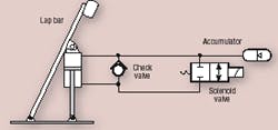
Obviously, heights of 400 ft instill a fear of falling, even though riders are securely held in their seats by redundant restraint systems. A primary restraint system of Top Thrill Dragster is a padded lap bar. Each lap bar uses a pair of hydraulic cylinders to hold it in place.
Referring to the diagram, each cylinder has its own holding circuit, so one assembly, shown, is redundant. An operator pushing down on the lap bar causes the pair of double-acting cylinders attached to it to retract. This forces fluid from the cap end of the cylinder into the rod end. A check valve in the line connecting the rod-end port to the capend port prevents the cylinder from extending, so the lap bar cannot move upward.
However, volume of the cap end of the cylinder is greater than that of the rod end. So when the cylinder retracts, excess fluid from the cap end flows into the accumulator.
Once the coaster train reaches the exit area, an electrical signal energizes the solenoid valve of all restraint circuits. When this occurs, the valve shifts, allowing fluid to flow freely from the rod end of the cylinder to the cap end. Pressurized fluid from the accumulator is also released and aids in lifting the lap bar.
Click here to watch a video of a ride on Top Thrill Dragster.
As pointed out in this article, Top Thrill Dragster requires about 10,000 hp to accelerate the 12,000 lb coaster to 120 mph in less than four seconds. Therefore, it is designed to store just enough energy to launch the coaster over the 400-ft hill — any more would be wasted energy. It's inevitable, then, that sometimes the coaster will not have enough energy to conquer the hill, so it will roll back to the launch site. And on a rare occasion, it will have just enough energy to reach the top of the hill and stay balanced there. Click here to see a video of when this happened — and how it was resolved.
-alh
This file type includes high resolution graphics and schematics when applicable.
