Proportional valves vs. servovalves
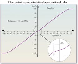
Continuing the discussion from last month, Figure 4 shows the characteristics of a generic proportional valve. The ISO 5598 definition of a servovalve is electrically modulated continuous control valve (3.2.131) in which the deadband is less than 3% of the valving element (3.2.759) stroke. The key feature of the flow metering graph in Figure 4 is the region of reduced gain at the zero crossing. (Note: the data in Figure 4 is not that of a real valve, but, rather, is an approximation of real valve data).
The definition of a proportional valve in ISO 5598 follows logically from the definition of a servovalve: electrically modulated continuous control valve (3.2.131) in which the deadband is greater than or equal to 3% of the valving element (3.2.759) stroke.
This reduced flow gain zone essentially is the overlap of the valve. In fact, the amount of overlap is very near 3%, so two different knowledgeable people might disagree as to whether Figure 4 depicts performance of a servovalve or a proportional valve. The ISO Working Group did not take up the specific analytical methods for interpreting the data. But the fact is that the gain at zero-crossing is reduced. So whoever interpreted the data in Figure 4 concluded that the width of the reduced gain zone exceeds 3% of total spool travel because the drawing is labeled as a proportional valve.
Open to interpretation
Adding to the confusion is the use of the term deadband to refer to the region of reduced flow gain. The deadband is not dead at all! Some flow metering remains, even with valves that have 10% and even 35% of overlap. It is all a matter of degree. Again, the ISO Working Group refused to take up the issues of quantifying the overlap, and manufacturers continue to fearlessly report it as if everyone would agree on the analytical method.
Some servovalve manufacturers will show a flow metering graph with some uncertainty in the zero-crossing characteristic. That is, because of manufacturing tolerances, the spool in any specific valve could be ground with under, critical, or over lap. The consequences to the user are that a change in the flow gain occurs at the center, and the gain could be increased (under lapped), critically lapped (negligible, or minimal gain change) or overlapped (reduced flow gain).
It is not uncommon for servovalve manufacturers to specify some minimum gain at zero-crossing in the case of a slight amount of overlap. For example, the claim in a manufacturer’s technical literature may be, “Reduced flow gain at null will not be less than 25% of flow gain outside the null zone.” In most applications, system performance using a valve with an overlap of 3% will not be significantly different from a critically lapped one. The null zone flow gain will be about 25% or more of the flow gain outside the null zone. However, with good valve models and simulation tools, we can explore the consequences of many of servo and proportional valve manufacturing aberrations.
Dealing with valve lap
Most proportional valves are deliberately designed and manufactured with a targeted amount of overlap, often more than 10%. This manufacturing cost is reasonable because:
• no flow grinding is needed,
• spools and bores don’t have to be matched sets, and
• human operators can locate the null zone easily in manually controlled systems while also providing continuous variability in flow throttling.
Complications can arise as users apply electronic compensating methods and use proportional valves in feedback control systems. Nearly all manufacturers of proportional valve driver amplifiers provide them with a feedback terminal, encouraging their use in closed-loop control systems.
Pressure metering and gain
Pressure gain is a servo or proportional valve characteristic that is often misunderstood by those who have not had specific training in servo and proportional technology. The misunderstanding comes from the conventional explanation of valve and output actuator interaction, which usually goes something like this: The operator centers the valve, which cuts off flow and causes the actuator to stop. Technically, this is not true. In fact, it’s more the opposite that is the case: the actuator stops, causing the flow to stop. This becomes an important distinction when dealing with servo and proportional valves and is absolutely vital in understanding the implications if feedback control is used. It is less important in manually controlled systems.
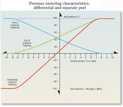
Moving on, Figure 5 shows the pressure metering curves for a low overlap (not more than about 4% or 5%) proportional valve. All the pressure metering in this valve takes place with only about 7% or 8% of rated current. Assuming a linear relationship exists between current and spool position, the pressure metering range would be the same. A good general rule is that pressure metering takes place in the overlap zone of spool travel, plus about 4% to 5%. Thus, a proportional valve with 22% overlap will meter pressure over about 27% of spool travel. A critically lapped servovalve will meter the pressure over about the center 4% or 5% of spool travel or input current. For all spool positions or input currents in excess of that, the work ports will either be at supply pressure or at zero (actually, at tank port) pressure.
Figure 5 shows both the per-port and the differential pressure metering curves. The differential pressure metering curve is merely the mathematical difference between the two work port pressures, or, it could be collected directly if the valve is tested with a differential pressure transducer connected between the two work ports.
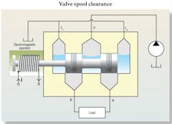
Pressure metering is a simple test procedure. However, referring to the overlapped valve of Figure 6, imagine removing the load from the work ports and connecting a pressure gauge in each work port. This means there will be no output flow during the test, even when the valve is shifted. Now imagine that the valve is fully shifted to route fluid out the A port (spool fully left).
What pressures would you expect to see on the two gauges? Of course, the A-port pressure would be at the supply pressure, and the B port pressure would be at or nearly zero. What would happen if the spool was to be shifted fully to the right? The pressure would be just the opposite, with the A-port low and the B port high. If the pressures changed, then some region of transition must exist somewhere in between. That region is at the center of the spool travel — that is, in the null zone of the valve. To collect the metering data, you need to slowly move the spool through the null zone and record the results as depicted in Figure 5. The greater the overlap, the wider the spread of the pressure metering zone.
Referring back to Figure 5, note that the control axis is valve input current, (control current), and the point where the two port pressures cross does not occur at zero current, but, rather, at a slightly negative value of about –0.5%. The drawing was made that way deliberately to make a point. This tells us that the valve is not nulled. The nulling procedure requires that the point of equal port pressures (zero differential pressure) coincides with zero current.


