*Editor's note: This article was originally published in 2011 and updated in June 2023.
Hydraulic reservoirs store the fluid necessary for the operation of hydraulic systems. Understanding the types available and how to specify the right reservoir for a given application will help to ensure optimized performance of hydraulic components and systems.
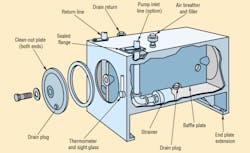
In addition to holding in reserve enough fluid to supply a system's varying needs, hydraulic reservoirs also provide:
- a large surface area to transfer heat from the fluid to the surrounding environment
- enough volume to let returning fluid slow down from a high entrance velocity, enabling heavier contaminants to settle and entrained air to escape
- a physical barrier (baffle) that separates fluid entering the reservoir from fluid entering the pump suction line
- air space above the fluid to accept air that bubbles out of the fluid
- access to remove used fluid and contaminants from the system and to add new fluid
- space for hot-fluid expansion, gravity drain-back from a system during shutdown, and storage of large volumes needed intermittently during peak periods of an operating cycle, and
- a convenient surface to mount other system components, if practical.
These are the traditional roles of reservoirs, however, new trends may present deviations from the norm. For example, new designs for hydraulic systems often call for reservoirs that are much smaller than those based on traditional rules of thumb. Because most systems warrant some special consideration, it is important to consult industry standards for minimum guidelines. Recommended Practice ANSI/(NFPA)/T3.16.2* addresses basic minimum design and construction features for reservoirs.
How to Size a Hydraulic Reservoir
The first variable to resolve when sizing a hydraulic reservoir is determining volume. A rule of thumb suggests that the reservoir's volume should equal three times the rated output of the system's fixed-displacement pump or mean flow rate of its variable-displacement pump. This means a system using a 5-gpm pump should have a 15-gal. reservoir. The rule suggests an adequate volume to allow the fluid to rest between work cycles for heat dissipation, contaminant settling, and deaeration.
Keep in mind that this is only a rule of thumb for initial sizing. In fact, the National Fluid Power Association's (NFPA) Recommended Practice states, "Previously, three times the pump capacity had been recommended. Due to today's system technology, design objectives have changed for economic reasons, such as space saving, minimizing oil usage, and overall system cost reductions."
Whether or not you choose to adhere to the traditional rule of thumb or follow the trend toward smaller reservoirs, be aware of parameters that may influence the reservoir size required. For example, some circuit components — such as large accumulators or cylinders — may involve large volumes of fluid. Therefore, a larger hydraulic reservoir may have to be specified so fluid level does not drop below the pump inlet regardless of pump flow.
Systems exposed to high ambient temperatures require a larger reservoir unless they incorporate a heat exchanger. Be sure to consider the substantial heat that can be generated within a hydraulic system. This heat is generated when the hydraulic system produces more power than is consumed by the load. A system operating for significant periods with pressurized fluid passing over a relief valve is a common example.
Reservoir size, therefore, often is determined primarily by the combination of highest fluid temperature and highest ambient temperature. All else being equal, the smaller the temperature difference between the two, the larger the surface area (and, therefore, volume) required to dissipate heat from fluid to the surrounding environment. Of course, if ambient temperature exceeds fluid temperature, a water-cooled or remote-mounted heat exchanger will be needed to cool the fluid.
For applications where space conservation is important, heat exchangers can reduce hydraulic reservoir size (and cost) dramatically. Keep in mind that the reservoir may not be full at all times, so it may not be dissipating heat through its full surface area.
The reservoir should contain additional space equal to at least 10% of its fluid capacity. This allows for thermal expansion of the fluid and gravity drain-back during shutdown, yet still provides a free fluid surface for deaeration. In any event, NFPA/T3.16.2 requires that maximum fluid capacity of the reservoir be marked permanently on its top plate.
The Pros and Cons of Smaller Hydraulic Reservoirs
A trend toward specifying smaller hydraulic reservoirs has emerged as a means of reaping economic benefits. A smaller reservoir is lighter, more compact, and less expensive to manufacture and maintain than one of traditional size. Moreover, a smaller reservoir reduces the total amount of fluid that can leak from a system – important from an environmental standpoint.
But specifying a smaller reservoir for a system must be accompanied by modifications that compensate for the lower volume of fluid contained in the reservoir. For example, because a smaller reservoir has less surface area for heat transfer, a heat exchanger may be necessary to maintain fluid temperature within requirements. Also, contaminants will not have as great an opportunity for settling, so high-capacity filters will be required to trap contaminants that would otherwise settle in the sump of the reservoir.
Perhaps the greatest challenge to using a smaller reservoir lies with removing air from the fluid. A traditional reservoir provides the opportunity for air to escape from fluid before it is drawn into the pump inlet. Providing too small a reservoir could allow aerated fluid to be drawn into the pump. This could cause cavitation and eventual damage or failure of the pump.
When specifying a small hydraulic reservoir, consider installing a flow diffuser which reduces the velocity of return fluid (typically to 1 ft./sec.), helps prevent foaming and agitation, and reduces potential pump cavitation from flow disturbances at the inlet. Another technique is to install a screen at an angle in the reservoir. The screen collects small bubbles, which join with others to form large bubbles that readily rise to the fluid's surface.
Perhaps the best way to prevent aerated fluid from being drawn into the pump is to prevent aeration of fluid in the first place by paying careful attention to fluid flow paths, velocities, and pressures when designing the hydraulic system.
READ MORE: Cylindrical reservoir breaks from convention
Understanding Reservoir Design Configurations
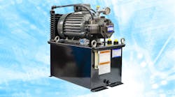
Hydraulic reservoirs are available in various design configurations. Rectangular reservoirs are a common type which traditionally have a hydraulic power unit comprised of a pump, electric motor, and other components mounted on top of the hydraulic reservoir tank. Therefore, the top of the reservoir must be structurally rigid enough to support these components, maintain alignments, and minimize vibration. An auxiliary plate may be mounted on top of the reservoir to meet these objectives. A big advantage of this configuration is that it allows easy access to the pump, motor, and accessories.
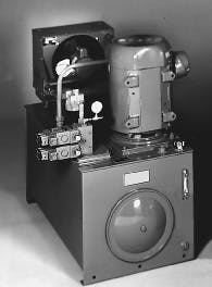
A current design trend has the electric motor mounted vertically, with the pump submerged in hydraulic fluid as seen in Figure 2 below. This conserves space, because the hydraulic reservoir can be made deeper and take up less floor space than one with traditional "bathtub" proportions. The submerged-pump design also eliminates external pump leakage, because any fluid leaking from the pump flows directly into the reservoir. In addition, the power unit is quieter, because the hydraulic fluid tends to damp pump noise.
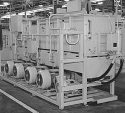
An alternate configuration positions the hydraulic reservoir above the pump and motor as shown in Figure 3 below. This overhead configuration provides the advantage of combining atmospheric pressure and the weight of the fluid column to flood (force fluid into) the pump inlet, which helps prevent cavitation. The reservoir's top cover can be removed to service internal components without disturbing the pump and motor.
The overhead reservoir may cause a problem with gravity-return drain lines, so an auxiliary pump may be needed to route fluid up to the reservoir. When noise is a problem, overhead hydraulic tanks provide the most convenient way to enclose the pump and electric motor within a noise suppression chamber.
Many applications use hydraulic reservoirs that combine characteristics of the different configurations. For example, an L-shaped reservoir combines the advantages of top- and base-mounted reservoirs — a flooded pump inlet and easy accessibility of components.
Reservoirs can also be pressurized to flood the pump. This pressure can come from an external source or from trapped air and fluid thermal expansion. A pressure-control valve allows filtered air to enter the reservoir when the fluid cools but prevents its release unless air inside reaches a threshold pressure.
Hydraulic Reservoir Shapes and Construction
There is no standard hydraulic reservoir shape. Geometrically, a square or a rectangular prism has the largest heat-transfer surface per unit volume. A cylindrical shape, on the other hand, may be more economical to fabricate. If the reservoir is shallow, wide, and long, it may take up more floor space than necessary and does not take full advantage of the heat-transfer surface of the walls.
Theoretically, because heat rises, the reservoir top holds the greatest potential for heat transfer to the atmosphere. However, in particularly dirty environments, contaminants often collect on the reservoir top and act as insulation. This reduces the effective heat transfer from the top of the reservoir, so reservoir sides could actually be the most effective heat transfer area in some instances.
On the other hand, a tall and narrow geometry conserves floor space and provides a large surface area for heat transfer from the sides. Depending on the application, however, this shape may not provide enough area at the top surface of the fluid to let air escape.
The reservoir should be strong and rigid enough to allow lifting and moving while full. Appropriate lift rings, lugs, or forklift provisions should be included.
READ MORE: Cylindrical reservoirs promote cleanliness
Various Reservoir Accessories Benefit Performance
There are several reservoir accessories available which can help to further optimize the performance of hydraulic systems. These hydraulic reservoir accessories can be used for:
- straining new fluid as it enters a system
- filtering air drawn into the reservoir as hydraulic fluid level rises and falls during system operation
- indicating fluid level in the reservoir
- indicating fluid temperature
- routing return fluid to minimize potential pump cavitation and improve heat transfer
- heating cold or low-viscosity fluids to necessary operating temperature, and
- removing ferrous contaminant particles from the fluid.
Fluid must be added to the hydraulic reservoir at startup, after cleanout, and to make up for losses. Two filler openings should permit reasonably rapid filling (at least 5 gpm each), intercept large contaminant particles from the new fluid, and either seal when closed or filter incoming air if vented as a breather. The openings should be on opposite sides or ends of the reservoir. Metal strainer screens of 30-mesh or finer should have internal metal guards and be attached so tools are necessary for removal. The filler cover should be permanently attached, and if it does not include a breather, a separate breather should be specified. In either case, 40-µm air filtration should be provided.
In addition to slowing down fluid returning to the reservoir, reducing foaming and pump cavitation from flow disturbances at the inlet, and providing fluid mixing without agitation, flow diffusers also reduce noise and the need for baffling. They are especially effective in small reservoirs with high flows and in deep reservoirs with a small floor area.
A fluid-level indicator should be located at each filler. Indicators should have high and low levels marked against a contrasting background to help maintain appropriate fluid level. An electronic level indicator can serve as a more sophisticated alternative. These devices use a variety of means to measure liquid level. Transducers produce a continuous output, and switches signal when liquid reaches a predetermined high or low level.
Fluid temperature measurement is not required by the NFPA standard, but a selection of thermometers is available, many in the same housing as the fluid-level indicator. (If high fluid temperature is a continuing problem, the heat source in the circuit should be identified and removed.) As with level indicators, a variety of electronic temperature indicators are available.
In either case, signals generated by these devices are routed to a display or control panel to provide operators with an indication of fluid status. Wiring a level or temperature switch into the machine's control can prevent equipment damage by shutting down the machine if fluid reaches a dangerously low level or high temperature.
After shutdown, or when the reservoir is exposed to colder temperatures, the fluid may be too cold for immediate operation. Cold fluid may become viscous or thick enough to prevent it from being drawn into the pump, causing pump cavitation or other problems that can damage components or cause system malfunctions.
A thermostatically controlled heater to warm fluid until its viscosity becomes compatible with the system solves this problem. Again, by wiring this thermostat into the system control, machine operation can be prevented until fluid reaches a minimum temperature.
Magnets can be placed in the reservoir to capture and remove metallic particles from the fluid stream. Fluid returning to the reservoir should be routed past in-tank magnets to collect as many ferrous particles as possible. Magnets should be checked periodically and cleaned to ensure continued maximum performance.
Although hydraulic filters are usually not considered reservoir accessories, almost all pump inlet strainers are located within the reservoir, and many other filters mount on or through reservoir surfaces. Because the inlet strainer is out of sight, a pressure gage will help indicate when cleaning is necessary.
Integral Hydraulic Reservoirs
In some systems, the hydraulic reservoir is built as an integral part of the equipment it serves. Because of the diversity of designs and special design practices, integral reservoirs are not addressed in the standard developed by NFPA and the American National Standards Institute (ANSI). They are used most often with mobile equipment, and their placement often is an afterthought, which necessitates custom-designed shapes for irregular areas.
A number of potential problems exist with integral reservoirs that require special consideration. These include:
- available space may limit size; because heat transfer capacity is a function of size, external oil coolers or heat exchangers may be needed
- irregular shape may require special baffling to properly route fluid
- surrounding equipment may limit convectional heat transfer
- service accessibility may be poor, and
- special heat shielding may be needed to isolate components or the operator from reservoir heat.
Hydraulic Reservoirs for Mobile Equipment
Mobile hydraulic reservoirs are expected to perform the same functions as their industrial counterparts — but usually under more adverse and less predictable operating conditions. Machine motion (which makes complex baffling systems necessary to prevent fluid sloshing) and extreme ambient temperatures are just two examples of the special problems designers of hydraulic systems for mobile equipment face.
Size and weight limitations may require mobile equipment to operate with reservoirs as small as the volume a pump discharges in a minute. This is roughly a third the size of a reservoir traditionally used in an industrial application. The space and shape limitations mobile equipment places on reservoirs requires that they often be custom designed. Cost, size, and weight must be minimized, while still maintaining adequate performance and efficiency.
When to Use Internal or External Filters?
Return filters are often placed inside the hydraulic reservoir tank to save space and to provide integral diffusion. One advantage of in-tank return filtration is that filling the tank through the filter helps ensure system cleanliness. However, it is important to ensure contaminants cannot fall into the hydraulic reservoir when a return filter element is changed.
Placing filters within the hydraulic tank provides a neat design but may promote contamination of an area that is difficult to keep clean. While more difficult to plumb, external return filters keep contaminants outside the hydraulic tank, and they are more easily accessible for servicing.
Magnets should be placed in the reservoir to trap ferrous particles. Dams and suction strainers also can be added to increase the effectiveness of the reservoir as a contaminant controller. Particle dams, placed between the return and suction areas of the hydraulic reservoir tank, help contain heavier particles that may have bypassed the return filters. Dams commonly consist of an angle plate that extends across the floor of the tank. The dam should be high enough to contain particles until the reservoir is routinely cleaned but low enough to prevent fluid from having to cascade over it. Dams also provide ideal mounting surfaces for magnets.
Locating a pump at or above fluid level and far away from the tank (more the rule than the exception with mobile equipment) usually prohibits the use of pump inlet filters. Suction strainers or filters should be considered as a form of last-chance pump protection when positive pump inlet conditions can be provided – as with a charge pump or pressurized reservoir. Pay attention to fluid temperature (especially during startup) when sizing suction filters if equipment will operate in cold climates and pumps cannot be disengaged during startup.
How to Choose Between Vented or Pressurized Reservoirs
An important design consideration is whether to specify a vented or pressurized reservoir. The major deciding factors are the location and inlet requirements of the pumps. The fluid level of the reservoir in many mobile applications is below the pump inlet. At best, if there is vacuum at the pump inlet, the pump may have to be derated. If inlet line losses are great enough, cavitation will occur. In these cases, pressurizing the reservoir will help maintain pump performance.
Any of three methods can be used to pressurize a reservoir on most mobile equipment:
- Use regulated compressed air from a machine's pneumatic system — the most effective method — if available.
- Trap the air within the reservoir clearance volume (above the fluid) and depend on thermal expansion of the fluid to compress this air, and thus pressurize the reservoir. A reservoir pressure cap holds pressure within the tank and relieves excess pressure.
- Tap pressurized air from the scavenge pump of a two-cycle diesel engine.
With pressurized reservoirs, consideration must be given to calculate stresses on reservoir walls, because even low pressures can exert substantial loads. For example, an internal pressure of only 3 psi applies a force of 1,800 lbs. on a 20- by 30-in. wall. This force, combined with weight of hydraulic fluid, plus G forces involved in mobile equipment, can produce stresses high enough to actually work harden a metal reservoir. Work hardening makes the metal more brittle, which eventually will cause leakage when the metal is exposed to continued stress.
Wall stresses should also be calculated for vented hydraulic reservoirs. High stresses develop quickly in large areas of flat plate. And again, weight of the fluid can cause large deflections. Furthermore, mounting peripheral equipment, such as ladders, to a reservoir increases the need to specify stiffening members and a thicker plate.
Proper Cleaning and Maintenance of Hydraulic Reservoirs
Servicing of hydraulic reservoirs must also be taken into account when developing or specifying them for an application. There must be provisions to drain both return and suction areas of the tank, especially if a dam is installed to separate them. Pipe couplings often are used, but SAE O-ring ports provide better sealing. Valving should also be provided to close off inlet lines when replacing pumps or other components that are mounted below fluid level.
This is often wishful thinking, but access should be provided for cleaning and maintaining the interior of the hydraulic reservoir tank. Ideally, hatches should be large enough to provide enough room for service personnel to maneuver cleaning tools. There should also be means for lighting each portion of the tank for inspection.
Download a PDF version of the original article.
* The industry standard for hydraulic reservoirs is contained in ANSI/(NFPA) T3.16.2 R1-1997 (R2005) Hydraulic fluid power – Design for Nonintegral Industrial Reservoirs developed by the American National Standards Institute (ANSI) and National Fluid Power Association (NFPA).
