Tough sugar cane surrenders to tougher hydraulic harvester
Sugar cane is grown in the tropical belt around the world. Planted at 1.5-m nominal row centers (actual rows vary from 0.5 to 1.8 m), the crop grows stalks 25 to 50 mm in diameter and 2 to 5 meters high. After 12 to 15 months, the canes are cut at their bases to harvest the crop. Each cut plant ratoons or regrows, and is ready for harvest again 12 or 13 months later. This cycle repeats three or four times, then the crop is plowed under, the ground re-cultivated, and new cane planted.
In many parts of the world, the harvest still is a manual operation. Sugar cane is one of the most difficult crops to harvest mechanically because of the size of the plants, varying crop density, the number of different cane varieties, and irregularities in growing patterns. For example: canes do not always grow erect. If heavy rain and winds occur during the growing season, the cane may be blown over or plants may collapse from the weight of the wet tops and the soft ground. These plants continue to grow, and the tops turn upward toward the sun so the cane takes the shape of a large hook.
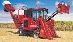
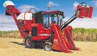
Case IH-Austoft took all these factors into account during the design of their versatile Series 7000 sugar-cane harvesters. These 325-hp self-propelled machines are built on tracks or rubber-tired wheels. The harvesters remove the cane tops, cut the cane off near ground level, chop it into billets, clean the billets, and load them into a transporter which drives alongside the harvester in the field — all in one operation.
When ready to go, the harvester straddles a row of cane. In front of the machine and about 3 m above the ground, the topper’s two gathering discs pull canes to a severing-knife drum. The knife cuts the top off the cane and discharges the severed top to the side of the machine. The topper incorporates three hydraulic motors.
Also out in front, a pair of crop dividers floats along the ground and separates one cane row from the next. This function is especially important when canes are recumbent. The crop dividers tend to comb the canes out and align them properly to feed into the machine. (Hydraulic cylinders adjust the height of these dividers above the ground.)
Underneath the harvester is the hydraulically driven, double-disc-type, reversible, 5-blade basecutter. Ahead of the basecutter, there are two feed rollers: a knock-down roller and a finned roller. The knock-down roller directs the cane off the crop dividers and the finned roller feeds the cane into the basecutter. There, counter-rotating discs cut the cane off at ground level or slightly below. (Using hydraulic cylinders, the operator pivots the harvester about its rear axle, and raises and lowers it on the front suspension to control the basecutter height.)
Additional feed rollers convey the cut cane from the basecutter to the choppers behind the cab. The lower rollers are fixed and the top rollers float independently to control the flow of cane into the choppers. The roller configuration allows any dirt and stones to drop out of the machine before reaching the choppers. The choppers cut the cane into 250-mm long billets, then pass them into the cleaning chamber. There, a hydraulically driven, 3-bladed extractor fan blows loose trash from the billets. This trash is discarded through a hood to the rear of the machine.
The cleaned billets next fall into the elevator (which can be slewed 90° to either side of the machine). The elevator conveys the billets up to another fan, where more trash is removed through the secondary extractor hood. The billets fall from the elevator’s head shaft — their descent controlled by a hydraulically positioned bin flap — into the transporter.
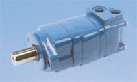
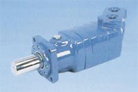
Hydraulics drives all functions on the harvester. A splitter box mounted to the rear of the engine holds seven pumps. Two variable-displacement, bi-directional piston pumps supply the transmission; five gear pumps supply the 33 motors and seven cylinders that power all the harvester functions. Unlike most other machines, the harvester’s engine runs at full speed to maximize power and pump efficiency. Hydraulic motor speeds are set based on this engine speed. (Cylinder circuits account for only 12 of the 220 gpm of hydraulic fluid circulating on the machine.) An oil cooler has a thermostatic bypass and temperature switch to maintain oil temperature between 70° and 80° C.
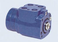
One gear pump supplies the basecutter motor, which also serves as a flow divider that drives the crop dividers and rollers downstream. A second gear pump supplies the chopper motor, which also divides the oil to supply the feed rollers. The third gear pump supplies the topper, cylinder functions, and optional side trims. The fourth gear pump supplies the extractor and the fifth supplies functions on the elevator. In the field, the operator has to steer, maintain the heights of the topper and basecutter, assure that the crop dividers are floating, adjust the bin flap to accommodate the accompanying transporter, and keep an eye on all other functions. To simplify these multiple tasks, the Series 7000 has hydraulic power steering, and its dual joysticks plus other electric-over-hydraulic controls are conveniently mounted on the operator’s arm rests for finger-tip actuation.
If the feed train stalls, the operator must stop the elevator and harvest functions, back up, and rewind the material out of the machine. The harvester has full power in rewind, so it is easy to recover from a stall in the field.
Mal Baker, general manager engineering at Case IH-Austoft, provided design details about this hydraulic application. His company exports these harvesters to more than 40 countries around the world.
Click here to see a video of the Case IH Austoft 7000 in action.
About the Author
Richard Schneider
Contributing Editor
Contributing Editor, has been affiliated with Hydraulics & Pneumatics for more than 30 years and served as chief editor from 1987 through 2000. He received a BSME from Cornell University and also completed additional courses at the Milwaukee School of Engineering. His diverse background in industry includes ten years with a fluid power distributor and a variety of other professional positions. He has also been active with the National Fluid Power Association and Fluid Power Society.

Leaders relevant to this article:
