Car crushers provide a dramatic illustration of the power of hydraulics. In a matter of seconds, cars that have taken the pounding of highways for thousands of miles are effortlessly reduced into a pile of scrap. The crushing makes subsequent handling more productive because three or even four crushed cards can fit into the same space as one whole car. This is the philosophy of recycling – squeeze out the empty space from scrap to reduce its size.
Power for car crushing
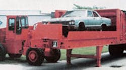
The No. 20 automatic car crusher, Figure 1, manufactured by Al-Jon Inc., Ottumwa, Iowa, flattens cars into a uniform slab approximately 10-in. thick and 6½–ft. wide; flattening the car does not significantly change its length. Cars can be crushed even if the engine has not been removed. Older cars or cars that have burned or suffered substantial front-end damage generally do not contain an engine worth removing, so the No. 20 eliminates the time and expense of removing a nearly worthless engine. Crushing the car with the engine intact also adds value to the scrap because it weighs more.
The No. 20 is powered by a 110-hp diesel engine operating at 2,000 rpm. This engine drives a tandem vane pump for high-low operation. It delivers high flow at relatively low pressure when no or little load is applied to the system, but when a threshold pressure is reached, it shifts to high-pressure operation. This high-low circuit allows the pump to generate flows to 100 gpm for fast cycling and still provide pressures to 2,100 psi. Fluid, filtered to 40 um, is contained in a 120-gal reservoir.
Automatic operation of the No. 20 is made possible by a programmable logic controller (PLC). Limit and pressure switches input signals to the PLC, which energizes or de-energizes the appropriate solenoid-controlled, pilot-operated valves.
Crushing sequence
A crushing cycle starts when the operator presses a button on a wireless remote control, usually located within the cab of a front-end loader or forklift. Remote control maximizes productivity: it allows one operator to load cars on the crusher’s receiving platform and start the crusher without leaving the vehicle.
The PLC commands valve solenoids to route pilot pressure to shift the feed-cylinder valve spool to extend. The 5-in. bore, 20-ft stroke feed cylinder has a 4-in. diameter chrome-plated rod that pushes the car into a crushing chamber and continues extending until the end of the car trips a proximity switch in the center of the chamber.
This proximity switch signal causes the PLC to de-energize the feed cylinder valve extend solenoid, causing the spring-centered spool to halt fluid flow to the cylinder. The PLC then energizes the crush cylinder valve solenoid that directs flow to the rod end of two 7-in. bore, 44-in. stroke cylinders.
The 3-in. chrome plated rods of these cylinders pull the crushing jaw downward, but because the crushing jaw pivots on a shorter moment arm than the cylinders, mechanical advantage multiplies the force exerted by the crushing jaw to 600,000 lb. Crushing continues until system pressure reaches 2100 psi, which trips a pressure switch that causes the PLC to command the valve spool to its center position. The PLC then signals the valve to reverse flow, so the crush cylinders begin extending, opening the crushing chamber.
Once the crush cylinders have extended, the PLC again commands the spool in the crush valve to center. The PLC also commands the feed valve to route fluid to the cap end of the feed cylinder. The feed cylinder then pushes the car farther into the crushing chamber; the just-crushed section at the leading end of the car exits the other end of the chamber. As this leading end emerges, it trips a limit switch to retract the crush cylinders. Crushing continues in sections until the entire car has been crushed — a cycle time of 60 to 90 sec.
Multiple crushing
Crushing car sections maximizes density because some sections of a car reduce more than others. For high-volume processors, some density can be sacrificed for throughput. Instead of crushing cards in “bites,” the LC 90, Figure 2, crushes an entire car in one compression using an overhead beam. The crushed cars are not as dense as those from the No. 20, but the LC 90 compensates with higher throughput. In fact, three or even four full-size cards can be crushed consecutively without vacating the crushing platform. The operator simply picks up a car, loads it on to the crushing platform, and activates the crusher with a wireless remote control. In less than a minute the LC 90 will be ready for another car, which can be placed directly on top of the one just crushed.
On the LC 90, a 150-hp diesel engine powers a pair of 52-gpm tandem gear pumps. A 120-gal reservoir supplies fluid filtered to 40 um through replaceable cartridge suction filters. System pressure is set at 1400 psi.
The 4-in. rods of two 10-in. bore by 84-in. stroke cylinders actuate each end of the crushing beam. Each cylinder works independently, so the crushing beam need not remain horizontal while crushing a car. Rod ends are mounted to self-aligning ball bushings to prevent side loads frm being transmitted to the cylinders. These cylinders are approved for operation at pressures to 1700 psi and tested to 3300 psi.
Dealing with tires
The marketability of scrap cars is clear: After an auto wrecking dealer has claimed valuable parts from a car and crushed it for more-economical transport and subsequent sale, a processor can shred the hulk and sell the scrap metal for subsequent remelting. Tires are another story.
Tires are undesirable in a shredder because they can cause shredder blades to jam or become prematurely dull. After all, manufacturers try to make tires virtually indestructible so they can stand up to the torturous pounding of thousands of miles of travel over country roads, city streets, and highways. Tires don’t become easier to process just because their useful life has been expended.
Simply disposing of tires becomes expensive when you consider that landfills often charge $3 per tire or more. This is because they are no easier to dispose of than they are to process. Tires are not only an eyesore, but their shape presents other, more serious problems. They can hold water to provide a nearly ideal breeding ground for insects. They also provide shelter for vermin. The biggest threat to the environment is the tremendous fire hazard they present; such a fire usually takes days to extinguish.
Auto wrecking dealers can shred tires in special shredders to reduce landfill fees. Shredded tires are much easier to dispose of because their shape can no longer breed insects, support vermin, or be the nearly inextinguishable fire hazard.
But this presents another problem: mounted tires cannot simply be thrown into a shredder. Removing tires from wheels poses another step in the recycling process which, of course, is added expense. Again, fluid power plays an integral role in a solution: the WC-500 wheel crusher, Figure 3, manufactured by Multitek Inc., Prentice, Wis.
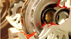
The WC-500 removes a tire from a rim and compresses the rim to make it more compact, which reduced shipping costs. Three cylinders simultaneously push inward on a mounted tire to crush the rim. When the cylinders retract, the rim remains compressed and can be lifted out of the tire. Rims can be crushed in under 15 sec, and a complete cycle occurs in 30 sec or less.
After depressurizing a tire, the operator places it on a platform and actuates a lever-operated valve that extends the three cylinders. Once the cylinders have crushed the rim, the operator reverses the valve lever to retract the cylinders. The operator picks up the cloverleaf-shaped wheel and round tire after cylinders have fully retracted. The WC-500 is now ready for the next operation.
A 35-hp gasoline engine powers a standard WC-500. It drives a gear pump, which generates flows to 18 gpm at 3,000 rpm. The 30-gal reservoir contains an in-tank reuseable lifetime filter and external spin-on filter. Each 4-in. bore cylinder has a 3-in. chrome-plated rod that can apply 38,000 lb of thrust to the rim.
The power package has fittings for connecting the WC-500 to auxiliary equipment such as tire cutters and multi-purpose crushers. This allows smaller operators to save money by having a single power package for multiple machines. The one power package can be used because only one machine generally is operated at a time.
Tire processing
After they have been separated from rims, tires can be shredded. Al-Jon makes a variety of machines for cutting tires into pieces convenient for landfill. Some cut tires into sections, while another cuts tires into a long ribbon. At the top of their line is their Portable Tire Processor. This fully automatic machine shreds whole tires into 2-in. by 2-in. chips that can be used for landfill, for fuel, or other forms of recycling. The machine processes up to150 tires per hr.
Al-Jon officials point out that the Portable Tire Processor is designed specifically for tire shredding rather than being a modification of a general-purpose shredder. It consists of three hydraulically driven shredders that successively reduce the size of tire pieces. A hydraulically driven conveyor carries shredded material to a 13-ft height for delivery to dumpsters, trailers, railroad cars, etc. A gerotor motor drives the conveyor.
The Portable Tire Processor is powered by a 150-hp diesel engine driving a four-section gear pump that delivers 150 gpm; operating pressure is 2400 psi. Other hydraulic components include a 200-gal reservoir with 40-µm filtration, three conveyor motors, and solenoid actuated, pilot-operated valves.
Click here to watch a video of the WC-500 in action.


