When explaining operation of complex equipment, such as an electro-hydraulic closed-loop position control, different approaches are adopted depending upon who the explanation is aimed at. Such explanations tend to fall into one of two categories — a full mathematical analysis for people with a strong control theory background, and a very simplistic instruction-manual style for everyone else.
The explanation that follows aims to fall in between these two extremes for the benefit of those who do not have a classical control theory background but nevertheless want to understand something of the why of a control system rather than just the what. If you can grasp the basic function of each component or adjustment, you may not be able to design a system from scratch — but you should have a much better understanding of how it works, how to set it up, and what to look for when something goes wrong.
Hop on board the seesaw
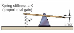
In order to follow through with the explanation, a little imagination is required, which involves thinking of a closed loop position control system as being like a child's seesaw, Figure 1. The control system is intended to position the output according to the input, at which point the system can be thought of as being in balance. When the output of the system coincides exactly with the input, then the seesaw will be in a perfectly horizontal position.
If the seesaw is balanced and placed in a level position with no disturbance, it will stay there. However, if even a small disturbing force acts on the seesaw, Figure 2, it will become unbalanced and will tilt. Relating this back to the control system, an out-of-level see-saw corresponds to a position error — a difference between input ( demanded position) and output ( actual position).
For the seesaw to regain its horizontal position, some form of self-correcting device needs to be added. If a spring is attached to one end, Figure 3, the seesaw will still be able to move, but the effect of the spring will be to tend to counteract any disturbance. Whether acting in tension or compression, the spring will always tend to move the seesaw back to the horizontal ( zero error) position.
The spring on the seesaw is analogous to the proportional term in a closed-loop position-control system. The amount of restoring force that the spring creates is directly proportional to the amount it is deflected (the out-of-level or position error). The stiffer the spring, the higher the restoring force for a given amount of error. This stiffness can be thought of as proportional gain in a closed-loop system.
Adding complexity
Simple systems may require no more visualization than this. Unfortunately however, springs in mechanical systems have a tendency to create undesirable oscillations. To counteract this, it may be necessary to introduce damping into the system. In the case of the seesaw, this could be achieved by using a damping piston or dashpot, similar to that used on a vehicle suspension.
The dashpot, Figure 4, will have no effect when the seesaw is stationary, but will act to steady it if oscillations occur. The amount of damping depends on the setting of the dashpot and the speed of movement of the seesaw — the rate of change of error. In mathematics, rate of change is known as the derivative (rate of change with time). The derivative gain is then represented by the setting of the dashpot, effectively the size of the hole or leakage path across the dashpot piston.
Now that the seesaw is free to move, it has a natural tendency to revert to a horizontal position and will not oscillate unduly. However, one other situation needs to be considered: The case where a large force acts on the seesaw, continuously creating a permanent outsole error. Using a stiffer spring (higher proportional gain) may reduce this error, but it cannot eliminate it altogether. (The spring needs to create a force to counteract the weight. Therefore, the spring must be stretched a certain amount to create this force). A stiffer spring may also have a tendency to make the system oscillate more.
In a control system, a permanent error between input and output is known as a steady state error and occurs typically when outside forces such as weight or wind pressure act on the system.
The only way to eliminate the steady state error on the seesaw would be to put an equal weight on the opposite side to balance the disturbance, Figure 5. If the disturbing weight varied, then the balance weight would also need to vary but this could be achieved by using a bucket containing varying amounts of water. All that is required now is a means of emptying and filling the bucket automatically depending upon the disturbing weight or tilt-angle of the seesaw.
The solution to this would be a mechanically operated water control valve linked to the end of the seesaw. The valve opens or closes to fill or empty the bucket, depending upon the direction of tilt. If the output is below the input (negative error) then the valve will open to allow water into the bucket thus increasing its weight. If the disturbing weight changes or is removed, the seesaw will tilt the opposite way (positive error) thus opening the valve to drain water from the bucket, Figure 6.
When the weight of the bucket balances the disturbing weight exactly, the seesaw will be level (zero error) and the valve will close to automatically maintain the correct amount of water in the bucket.
The volume of water in the bucket at any one time is thus dependent upon both the magnitude of the error (out-of-level) and the length of time for which the error has existed. In mathematics this is known as the integral term.
When the error in the system (slope of the seesaw) is large, the water valve will tend to open wide and the bucket will fill and empty quite quickly. (The flow rating of the valve can be thought of as the integral gain). However, disturbances in the system may vary even more quickly, so the amount of water in the bucket may always lag behind what is really needed to balance the seesaw at any one time. The effect of this is to cause instability in the system whereby the seesaw may move violently from one extreme position to another resulting in a much larger error than the one it was intended to correct.
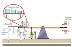
A possible solution would be to limit the size of bucket used ( integrator limit) to that required to just barely balance the largest expected disturbance and no more.
A more effective method may be to use the integrator reset function. This can be thought of as a large solenoid valve that, when energized, rapidly drains all of the water from the bucket. This valve could be held energized to drain the bucket when the error is large and use of the integrator would be problematic (i.e. during rapid changes in the system). Then, when the error reduces to a relatively small value, the valve could be de-energized (integrator switched back in) thus enabling the integrator bucket to eliminate the residual steady-state error.
An effective way of switching the integrator in and out is to use an error "window" detector, which can be thought of as two limit switches (LS1 and LS2) monitoring the seesaw movement, Figure 7. When the seesaw is within the two limits (small error) the integrator is in use, but outside of either limit (large error), the solenoid valve is energized and the integrator is reset (bucket drained). The height of the window can be adjusted depending upon the system characteristics.
Visualizing the system in this way helps to understand the basic rules of thumb of a PID position control system:
- Increasing the P gain (stiffer spring) may result in a more accurate, faster responding system but may also create a more oscillatory movement
- Increasing the D gain (more damping) will tend to reduce the oscillations in a system but may also slow its response, and
- Increasing the I gain (higher water flow) will likely reduce the stability of the system, but it can effectively eliminate steady-state errors when used with care.
Although the analogy is not perfect, it should be close enough for the visualization to help the understanding process and go some way towards explaining what the "knob in the top left hand corner" actually is.
Steve Skinner is European training manager, Eaton Hydraulics, Havant, U.K. He can be reached at [email protected].
About the Author

Leaders relevant to this article:


