Integrated Circuits Cut System Size, Complexity, and Cost
Content has been updated as of Oct. 13, 2021.
Paralleling the trend toward compactness in the world of microelectronics, integrated circuits can provide significant benefits in a fluidic system. By simplifying the system design, they save space and minimize overall system cost. Conventional systems route fluid from a power source through hose and tubing to a variety of line-mounted valves and actuators and then back to the power source.
In an integrated circuit design, hose and tubing may still carry fluid from the power source to a variety of valves, but most of these valves are contained within a single manifold, located wherever there is available space on a machine. Because integrated circuits have fewer separate components and connections, they also have fewer potential leakage points, lower internal volumes, easier assembly into equipment and higher reliability.
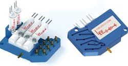
Conventional manifold designs are populated with 3-port (left) and 2-port (right) HDI platform solenoid valves. Barb ports enable them to be integrated easily into any application.
Although often found in lower pressure medical and scientific instrument applications, integrated circuits can provide many of the same benefits in a broader range of hydraulic and pneumatic systems by consolidating components within the manifold.
An integrated fluidic circuit consists of a manifold containing multiple pressure-, directional-, and sometimes proportional-control valves. In some cases, it also may contain pumps, filters, actuators or any combination of these to form a completely self-contained system. Most integrated circuits, however, consist of a manifold that incorporates inlet and outlet ports, cartridge or subplate-mounted valves (or both), and a network of internal passages that route fluid through branch circuits of the system.
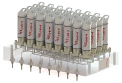
Multi-layered integrated circuit manifold is populated with The Lee Company’s LFV series solenoid valves.
Manufacturing Techniques
The Lee Co., Westbrook, Conn., is a manufacturer of integrated fluidic circuits, miniature valves, and other components using several different techniques to create manifolds. Techniques include conventional machining, a multi-layered approach and a technique they call “ant farm”.
The conventional machining approach is used mainly when the valve count is minimal, and the flow paths are straightforward. The design pattern of drilled passages allows the valves to be located as desired, with some limitations, because the drilled passages must be straight, and superfluous construction passageways must be plugged. Integrating miniature valves into a common fluid manifold using conventional cross-drilled machining is a major step toward simplifying otherwise complex valve and fluid passage configurations that once required a network of numerous tubes and hoses.
A multi-layered manifold is used when the functional requirements are more complex, such as in applications with a higher valve count. This manifold design is created by stacking multiple layers of plates that contain different milled or otherwise machined passages. The plates are then bonded together using epoxy, diffusion or solvent welding, which allows the valves, pumps, and other fluidic sub-components to be located where most appropriate for the specific application.
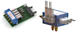
Ant Farm technique integrates multiple styles of HDI platform valves (plug-in and face mount) to accommodate a system’s specific space constraints and flow schematic requirements. Image at right shows the intricate flow paths that complete the internal circuit, with the bond plate partially cut away.
The Ant Farm technique involves machining a series of intricate flow paths or channels into the face of the manifold. After the machining operation, a plate is bonded over the flow passages to complete the circuit. In complex applications, the channels can be milled into more than one face of the manifold block. This machining technique further reduces the overall manifold size compared to the other technologies and also facilitates building a modular design.
The modular design can include provisions in the fluid passage for O-rings to provide a seal between different sections of the manifold when they are mounted together. This Erector Set approach gives the designer more flexibility, especially if the application requires a distribution plate to redirect or prevent flow from one passage to another between sections. It also allows the designer to use a spacer plate to increase dimensions between sections when necessary to accommodate an oversized component or obstruction on the mounting surface.
Using a combination of these techniques, multiple discrete components can be incorporated into a single unit, further reducing the number of connections, the need for a second manifold and overall package size. This also reduces assembly time during equipment production.
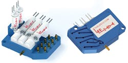
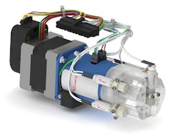
This manifold design integrates HDI platform solenoid valves into an LPV series pump with a custom port head.
Integrated Circuit Advantages
Because they are designed, manufactured, and tested by a single source, integrated fluidic circuits offer greater reliability and accountability. Concentrating multiple components in the manifold package lowers assembly and installation costs while also reducing weight and minimizing space requirements. Manifold-mountable components can include solenoid valves, pumps and components such as restrictors, filters and check valves. Single fluid fittings and gang-interface connectors also can be included. In addition, electrical components such as pressure sensors, connectors and circuit boards can be integrated into the manifold design. Furthermore, manufacturers frequently will warrant the assembly as a single part number.
About the Author
Ray I. Scroggins
Principal and Founder
Ray I. Scroggins is a frequent writer on subjects that include technology, manufacturing, construction and business. He holds degrees in business and engineering and specializes in writing feature articles for a wide range of business and trade publications. He is the principal of Scroggins Associates, LLC, a public relations firm he founded in 1984 and is based in Las Cruces, NM.

Leaders relevant to this article:
