Rotary actuators can mount right at the equipment joint without taking up the long stroke lengths required of cylinders. Rotary actuators also are not limited to the 90° pivot arc typical of cylinders; they can achieve arc lengths of 180°, 360°, or even 720° or more, depending on the configuration.
Rotary actuator designs
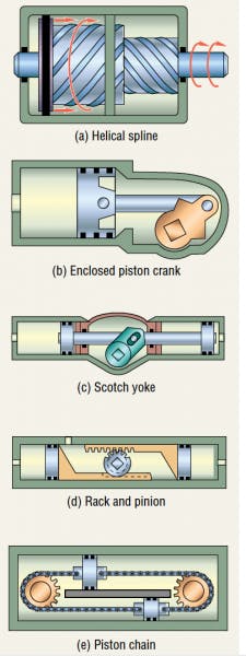
The helical-spline actuator sometimes referred to as a piston and helix or sliding spline actuator, has a long, slender configuration and uses a sliding helical splined gear operating concept to convert linear piston motion into shaft rotation. It is composed of a cylindrically shaped housing and two moving parts: the shaft and the annular piston sleeve. Helical spline teeth machined on the shaft engage a matching complement of splines on the inside diameter of the piston. The outside diameter of the piston sleeve carries a second set of helical splines that engages a ring gear integral with the housing, Figure 1(a).
The piston sleeve is hydraulically sealed between the housing and shaft. When hydraulic pressure is applied to the port to the left of the piston, three events occur simultaneously. The piston sleeve is displaced axially, moving to the right; it rotates clockwise (as viewed from the output shaft) as the gearing on its outside diameter and the housing's ring gear forces its rotation; and the gearing on the inside diameter of the piston sleeve causes the shaft to rotate clockwise. Applying pressure to the alternate port returns the piston sleeve to its original starting position and rotates the shaft counterclockwise.
The double helix, opposite hand design of the gear sets compound the rotation of the shaft, so its rotation is considerably more than that of the piston sleeve. For 30° helix designs, the rotation of the shaft is almost twice that of the piston sleeve, for 45° helix designs, it is even more. Features of this design include high torque from a compact configuration, constant torque through full angle of rotation, no internal leakage, and holding torque approximately two times the forward driving torque. With all gearing, moving parts, and bearings constantly bathed in hydraulic oil, helical actuators are virtually maintenance-free.
Because the effective hydraulic area is equal on both sides of the piston, equal torque is produced in the clockwise and counterclockwise directions. Average mechanical efficiency is about 70%. Since the angle of rotation is determined by actuator length, and because there are no internal barriers as in vane designs, any rotation is theoretically possible. Conversely, an appropriate internal stop tube can limit the rotation of an actuator to almost any intermediate angle. Most helical actuators, however, are available with 90°, 180°, and 360° rotations as standard. Due to the clearance needed between the internal spline teeth, helical actuators exhibit some backlash, typically ½° to 1° for smaller models and less for larger models.
Single-shaft designs are used where torque output is the primary factor in selecting the most economical actuator for the application. The double shaft extension with foot mounted housings is frequently used as a stable power hinge for heavy duty implements, tools, booms, cranes, and various machine components. Some helical actuators are also available with large diameter, drilled and tapped shaft flanges that permit loads to be bolt-mounted directly to the actuator. Hollow shaft designs are yet another option. Torque is directly proportional to pressure, and output torque can reach approximately 700,000 lb-in. with 3,000-psi fluid pressure.
An enclosed piston crank actuator, Figure 1(b), has an adjustable arc of up to about 100°. This actuator is compact and has few mechanical problems. Built-in bearing support overcomes side thrust forces. Fail-safe versions are equipped with a spring that returns the shaft to a safe position in case of power failure or loss of fluid. Torque generation follows a sinusoidal distribution. Maximum torque is produced at mid-stroke. Therefore, these actuators should be selected to drive a load based on their minimum torque.
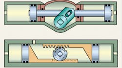
A scotch-yoke actuator, Figure 1(c), has two pistons connected rigidly by a common rod. The central drive pin on the rod engages a double yoke keyed to the output shaft which turns through arcs to 90° maximum. Torque outputs at the beginning and end of the stroke (breaking torque) is twice that at mid-point (running torque). This characteristic is efficient because many applications require high breaking torques to move and accelerate the load. Fail-safe, single-acting, and double-acting models are available. Efficiencies range from 70% to 95%.
In a rack-and-pinion actuator, Figure 1(d), a long piston with one side machined into a rack engages a pinion to turn the output shaft. This gearset principle is adaptable for use in fail-safe, single-acting and double-acting models. Where balanced loading on the bearings is required, two bi-directional pistons with parallel racks are used; both racks engage the one centrally-located pinion. Rotation to 1,800° and torque to 50 million lb-in. are available. Torque is constant and equal in both directions.
Multiple-position rack-and-pinion actuators are available that rotate the output shaft to several positions by varying the pressure porting. Output positions can be in any sequence, allowing the actuator to stop at or pass any intermediate position.
Rack-and-pinion actuators are particularly useful for heavy-duty applications because they tolerate heavy side and end loads and can accommodate large bearings. Because of their constant torque output characteristics and resistance to drift, they are often used for precision control. Efficiencies range from 85% to 92% in single rack models and from 92% to 97% for double rack models.
In a piston-chain actuator, Figure 1(e), a circular drive chain is held taut over two sprockets. One sprocket converts linear motion into torque output; an idler sprocket maintains tension. Two piston-shaped links are located at equal distances on the chain; one piston is larger than the other. The housing containing the mechanism has two parallel piston chambers and a port on each of the two opposite ends. Pressurized fluid entering a port acts against both pistons; the chain moves in the same direction as the larger piston because of the differential forces being exerted. The smaller piston seals the return side of the chain to prevent fluid leakage. Rotation is reversed by reversing porting.
A piston-chain actuator provides rotation to five complete turns and torques to 23,500 lb-in. The design is limited by the strength of the chain and sprocket, and by its bulk for applications requiring extremely high torques. Torque is constant throughout the stroke.
Bladder and vane actuators
In a bladder actuator, Figure 2(a), the output shaft is driven by the expansion and contraction of a pair of bladders. When one bladder is pressurized, it pushes against a cup-shaped lever arm, rotating the shaft through an arc of up to 100°. A 4-way valve controls oil or air flow so that while one bladder is pressurized the other is exhausted.
Because this type of actuator has zero internal leakage, it is highly accurate, and insensitive to contamination. Almost any fluid medium can be used if the bladder is chemically compatible; special housing materials are not necessary. This actuator can transmit torque to 2,750 lb-in.
Another bladder design uses a rack-and-pinion mechanism driven back and forth by expanding and contracting air bags. The bags hold precharges indefinitely and provide rotation to 90° or 180°. Highest torque is at the beginning of the rotation cycle. Torques to 45,000 lb-in are possible.
A single-vane actuator, Fig. 2(b), has a cylindrical chamber in which a vane connected to a drive shaft rotates through an arc to 280°. Two ports are separated by a stationary barrier. Differential pressure applied across the vane rotates the drive shaft until the vane meets the barrier. Rotation is reversed by reversing pressure fluid at the inlet and outlet ports.
A double-vane actuator, Figure 2(c), has two diametrically opposed vanes and barriers. This construction provides twice the torque in the same space as a single-vane actuator, however, rotation is generally limited to 100°.
Vane actuators are easy to service because they have fewer parts and less-critical fits than many other types of rotary actuators. Their mechanical efficiencies range from 80% to 95%, depending on construction and application. The square corners of the vanes make sealing a challenge, and internal bypass leakage can be common in vane-type actuators. Position-holding may be limited without external controls. Vane-type actuators transmit torques to 700,000 lb-in.
Mounting
To avoid excessive wear and premature failure, it is essential that very little or no thrust or overhung load be imposed on the actuator's output shaft unless it is equipped with bearings (such as tapered-roller bearings) to accommodate these loads. Use a flexible shaft coupling to eliminate side loading due to shaft misalignment. When side loading is unavoidable, support the output shaft with auxiliary bearings if the actuator is not equipped with adequate bearings to support such a load. Actuators coupled to gear trains belong in this category. Some helical and rack-and-pinion designs are available with integral bearings that can support significant overhung loads without additional external bearings.
To bleed trapped air, mount the actuator so the supply ports are on top. Or provide a suitable air bleeding device for the system. Larger rotary actuators often have built-in bleed valves.
In continuous-cycling applications, where hot hydraulic fluid may collect near the actuator, arrange for greater fluid circulation. Heat exchangers may be required. Do not install rotary actuators where contaminants are likely to collect — for example, at the system's low point.
Applications
Rotary actuators are used for mixing, dumping, intermittent feeding, screw clamping, continuous rotation, turning over, automated transfer, providing constant tension, and material handling. They are also suitable for turning, toggle clamping, indexing, positioning, oscillating, lifting, opening, closing, pushing, pulling, and lowering.
For example, in the steel industry, they up-end coils, turnstiles, and rollover devices, and tilt electric furnaces. In material handling, they switch conveyors, turn and position container clamps on lift trucks, tension, guide, operate valves, and brake. In marine operations they open and close hatches, swing cargo handling gear, operate booms and all types of large valves, position hydrofoils, and control steering.
They also perform such tasks as jib boom and work platform rotation on self-propelled aerial lifts, tool and implement positioning on construction equipment, percussion drill positioning on underground mining machinery, and hydraulic power steering on slip-form paving machines and piggyback forklifts.
For linear motion?
An actuator that rotates at constant speed can move heavy loads very efficiently in a linear direction by using a harmonic motion mechanical linkage. The harmonic motion produced offers a maximum mechanical advantage at the beginning of the stroke to accelerate the load quickly. Halfway through the stroke the load is at maximum velocity. The deceleration half of the stroke is a mirror image of the acceleration half. Heavy loads are slowed automatically and stopped with a force equal to that originally used to accelerate the load.
Automatic advance and return of a load at maximum speed can be obtained by using a 360° rotary actuator connected to a linkage rather than a 180° actuator. During deceleration, energy is not transmitted back into the hydraulic system but is used by the actuator to work the linked load. Less hydraulic fluid and horsepower is necessary. To size actuators for such applications, determine friction losses and the force needed to accelerate and decelerate the load.


