Engineering Essentials: Pressure Gauges & Flow Meters
Download this article in .PDF format
The majority of gauges for measuring pressure have one characteristic in common: the pressure being measured is the only source of energy required to provide a visual indication of static pressure. Some form of elastic chamber inside the gauge case converts the pressure to motion, which is translated through suitable links, levers, and gearing into movement of a pointer across an indicating scale. Three types of elastic chambers are commonly used in gauges for fluid power systems:
- C-shaped, spiral, and helical Bourdon tubes
- bellows, and
- single and multicapsule stacks.
Bourdon-tube designs
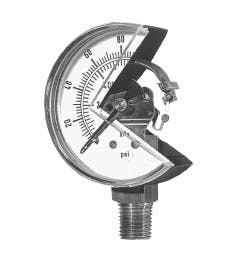
Since the invention of the Bourdon-tube gauge more than a century ago, pressure gauge manufacturers have been developing different types of gauges to meet specific needs without ever changing the basic principle of the Bourdon tube's operation. Bourdon-tube gauges, Figure 1, are now commonly available to measure a wide range of gauge, absolute, sealed, and differential pressures, plus vacuum.
They are manufactured to an accuracy as high as 0.1% of span and in dial diameters from 11/2 to 16 in. A variety of accessories can extend their performance and usefulness. For example, snubbers and gauge isolators can be installed to protect the sensitive internal workings of the gauge from pressure spikes. The availability of Bourdon-tube pressure gauges to meet specific needs, coupled with their inherent ruggedness, simplicity, and low cost has resulted in their wide use in many applications.
Gauges using C-shaped Bourdon tubes as the elastic chamber - the type shown in Figure 1 - are by far the most common. Pressurized fluid enters the stem at the bottom (which is sometimes center-back-mounted instead) and passes into the Bourdon tube. The tube has a flattened cross section and is sealed at its tip. Any pressure in the tube in excess of the external pressure (usually atmospheric) causes the Bourdon tube to elastically change its shape to a more circular cross section.
This change in shape of the cross section tends to straighten the C-shape of the Bourdon tube. With the bottom stem end fixed, the straightening causes the tip at the opposite end to move a short distance - 1/16 to 1/2 in., depending on the size of the tube. A mechanical movement then transmits this tip motion to a gear train that rotates an indicating pointer over a graduated scale to display the applied pressure. Often, a movement is incorporated to provide mechanical advantage to multiply the relatively short movement of the tube tip.
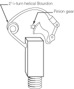
Bourdon tubes also may be made in the form of a spiral, Figure 2, or a helix, Figure 3. Each uses a long length of flattened tubing to provide increased tip travel. This does not change the operating principle of the Bourdon tube, but produces tip motion equal to the sum of the individual motions that would result from each part of the spiral or helix considered as a C-shape. Small-diameter spirals and helices can be manufactured to provide enough motion to drive the indicating pointer directly through an arc up to 270° without having to use a multiplying movement. Alternatively, they may be manufactured to be used in conjunction with a multiplying movement. In this case, the required motion is distributed over several turns, resulting in lower stress in the Bourdon material. This improves fatigue life when compared to a C-shaped Bourdon tube in the same pressure range.
Bellows and diaphragms
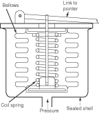
Low-pressure applications do not generate enough force in the Bourdon tube to operate the multiplying mechanism; therefore, Bourdon-tube gauges are not generally used for pressure spans under 12 psi. For these ranges, some other form of elastic chamber must be used, a metallic bellows, Figure 4, for example. These bellows generally are made by forming thin-wall tubing. However, to obtain a reasonable fatigue life and motion that is more linear with pressure, a coil spring supplements the inherent spring rate of the bellows. These spring-loaded bellows gauges generally are used in pressure ranges having spans to 100 psi and to 1 in. Hg.
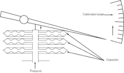
Metallic diaphragms also are used as the elastic chamber in low-pressure gauges. A diaphragm plate is formed from thin sheet metal into a shallow cup having concentric corrugations. To make an element with a low spring rate that generates substantial deflection from a small change in pressure, two plates can be soft soldered, brazed, or welded at their periphery to form a capsule, and additional capsules can be joined at their centers to form a stack, Figure 5.
Generally, the measured pressure is applied to the interior of the element and no supplemental coil springs are used. A 2-in.-diameter capsule (two plates) will provide about 0.060 in. of motion without exceeding the elastic limit of the material. This is usually enough to operate a high-ratio multiplying movement because diaphragm deflection can transmit high force.
Diaphragm elements often are used in gauges to indicate absolute pressure. In this form, the diaphragm element is evacuated. sealed, and mounted within a closed chamber. The pressure to be measured is admitted to the closed chamber and surrounds the diaphragm element. Changes in the measured pressure cause the element to deflect, but because atmospheric pressure is excluded and has no effect on the indication, the gauge may be calibrated in terms of absolute pressure. If the applied pressure is atmospheric pressure, the gauge is known as a barometer.
Diaphragm elements also may be used in an opposing arrangement. By evacuating one side of the assembly, the gauge can indicate absolute pressure. If a pressure is applied to one side of the assembly, and a second pressure is applied to the other side, then the differential pressure will be indicated. The differential pressure is limited with respect to the static pressure that can be applied. That is, the gauge may be suitable to indicate between 10 psi and 12 psi, but not be suitable to indicate between 100 psi and 102 psi. Also, the consequence of inadvertently applying full pressure to one side of the element and no pressure to the other side of the element must be considered.
Selection
Specifying a pressure gauge involves a number of considerations:
- connection size - nominal size of the port or fitting into which the gauge will be threaded, male or female, and thread size
- mounting configuration - bottom or back-center stem mounted or panel mounted
- dial size - large enough to be seen clearly from a distance but small enough to prevent taking up excessive space
- units of measure - determine whether the dial should be calibrated in psi, bar, kPa, etc. Many manufacturers offer gauges with dual-dimensioned scales
- materials of construction - gauges may have a glass or plastic crystal, metal or plastic case, and usually a brass connection. Ensure that materials are compatible with the environment and fluid
- dry or liquid filled - liquid-filled gauges generally contain glycerin to dampen effects of shock and vibration, and provide continuous lubrication of the movement to extend life, and
- pressure range - as a rule of thumb, select a gauge with a maximum pressure reading twice that of the anticipated measured pressure. This provides a safety margin to prevent temporary high-pressure pulsations or spikes from damaging the gauge.
Options and accessories
A variety of options and accessories are available to enhance life and operation of gauges. Digital readout is accomplished by mounting a strain gauge to the sensing element and using on-board electronics to convert the strain induced by pressure into digital readout on an LED or LCD panel. Digital gauges require a power source - generally a long-life battery - and may use a switch so that power is consumed only when a button is pushed to read the pressure.
A gauge isolator, mounted between the gauge and circuit, prevents the gauge from being exposed to fluid pressure unless a button is pushed. In this manner, the gauge is not exposed to pressure spikes and pulsations unless they occur when pressure is being read.
Orifices or snubbers protect gauges by smoothing out pressure fluctuations seen by the gauge. Snubbers may cause gauges to respond sluggishly, but can extend life by damping rapid pressure fluctuations. To help protect the gauge from external physical shock, case protectors can be used, which encapsulate the gauge in rubber.
A wide variety of other useful options - such as an integral adjustable pressure switch - are available from manufacturers to make pressure gauges even more versatile.
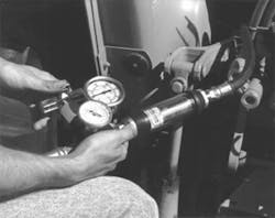
Unlike pressure gauges, which have been permanently mounted on the vast majority of hydraulic and pneumatic systems for decades, flowmeters continue to be used primarily for testing to assess the performance of a system, Figure 6. Systems requiring continuous monitoring of flow generally use electronic flow sensors rather than flow meters, which require no power.
Electronic flow sensors use a variety of sensing elements (turbines, positive-displacement chambers, differential-pressure measurement, etc.) to generate an electronic signal proportional to or otherwise representative of flow. This signal is then routed to an electronic display panel or control circuit. However, flow sensors produce no visual indication of flow by themselves, and they need some source of external power to transmit a signal to an analog or digital display.
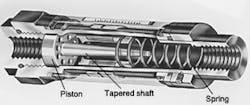
Self-contained flowmeters, on the other hand, rely on the dynamics of flow to provide a visual indication of flow. Although design details differ from one manufacturer to another, flow meters operate on the principle of dynamic pressure. The main components are a tapered shaft and spring-loaded piston, Figure 7.
With no fluid flow, the actuating spring pushes the piston to its left-most position. As fluid enters from the left side, pressure acts against the spring and builds to open the orifice formed between the ID of the piston and OD of the tapered shaft by pushing the piston to the right. As the piston is pushed farther to the right, the orifice area increases because the effective area of the tapered shaft decreases. Eventually, the orifice area will be large enough so that dynamic pressure from flow equals the opposing spring force. The position of the piston in equilibrium, then, provides an indication of flow.
For some applications, flow can be measured directly by comparing the piston position to a calibrated scale marked on the flow meter's transparent outer case. For most hydraulic applications, however, the piston usually has a magnet embedded that moves a follower collar. Position of the collar can then be compared to a calibrated scale.
Because flow indication depends on fluid dynamics, changes in a fluid's physical properties can affect readings. This is because a flowmeter is calibrated to a fluid having a certain specific gravity within a range of viscosities. A wide deviation in temperature can change a hydraulic fluid's specific gravity and viscosity, so if a flowmeter is used when the fluid is very hot or very cold, flow readings may not conform to manufacturers' specifications. However, because most equipment is tested under operating conditions, readings generally should fall within manufacturers' specifications for accuracy.
