This file type includes high resolution graphics and schematics when applicable.
A position transducer typically consists of two fundamental parts. One part remains fixed in position while the other part moves with the mechanism whose displacement is being measured. The exact nature, and therefore the size, of the fixed and moving portions depend on the sensing technology being used. Some transducers are intended to be mounted integrally to the mechanism, while others are designed to be mounted externally.
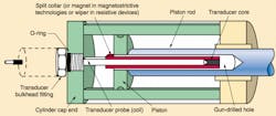
If a transducer is configured for mounting inside a cylinder, a hole usually is drilled down the center of the piston rod, and the cylinder end cap is machined to accommodate the transducer. This method usually consumes the least amount of space, but makes the transducer less accessible than mounting it externally. Mounting the transducer alongside the cylinder eliminates the time, effort, and expense of machining, but exposes the transducer to the environment. A protective enclosure can be used to shield the transducer from certain hostile conditions, but severe applications generally necessitate integrating the transducer into the relatively safe confines of the cylinder.
An electrical power source is required for all position transducers. The power is applied to one of the two fundamental parts. The other part is passive and does not require power. Normally, it is desirable to have the powered part be stationary to avoid problems associated with moving cables, cable strain, and cable routing. In addition to position/displacement, these transducers, through supporting electronics, can provide speed/velocity or acceleration.
Primary consideration should be given to the mounting space available and type of electric power to be used when selecting a transducer. A transducer that requires 120-V AC is not as appropriate for mobile equipment as one that needs 12-V DC. Additional consideration should be given to the application's environmental conditions.
Output from the position transducer can be a signal, whose amplitude is proportional to position (i.e. an analog voltage or current signal), or it can be proportional to time (i.e. a digital pulse whose duration is proportional to position). The third typical output is digital. This can be a series of pulses where each pulse represents movement of a fixed increment, or it may be a unique code for each measured position.
Types of position transducers
There are a variety of transducer designs used in a vast array of relatively long-stroke applications. The inherent design of a particular type usually determines whether or not it is suitable for a specific fluid power application.
Encoders - Encoders are non-contact digital devices that, in their simplest configuration, provide a defined number of pulses per revolution or per unit of linear displacement. Encoders produce digital pulses typically in 5-V DC, by consecutively completing and breaking an electronic circuit. This on/off sequence allows changes in position to be detected and measured. There are two typical transduction methods used in encoders; optical and magnetic.
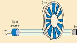
An optical encoder, Figure 1, consists of a light source, a light sensor, and a grid. The grid can be constructed of glass, metal, or plastic. It consists of alternate transparent and opaque areas that either allow or prohibit the passage of light from source to the sensor. This blocking and unblocking causes the associated electronics to generate a string of pulses. Magnetic encoders replace the grid with magnets, and the light source and sensor are replaced with devices that sense the changes in magnetic fields.
There are two types of encoders, incremental optical encoders (such as the arrangement shown in Figure 1) and absolute encoders.
For incremental encoders, a separate electronic controller determines position by counting the pulses. Incremental encoders, whether linear or rotary, will lose position when the electrical power is removed. Because counting must commence from a known point, a reference or home position has to be established when first powering up the encoder and its electronics. In practice, the operator of a machine generally initiates a homing routine to set the reference position before the machine is brought into use.
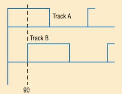
A second pulse output is added that is 90° out of phase with the first output so that an incremental encoder can determine direction. This phase shift is referred to as quadrature output, Figure 2, and it allows the controller to determine direction of travel and eliminate false counts caused by vibration when motion has stopped. A third output generates a single index pulse at a discrete position. This output is generally used for homing or indexing routines and for counting turns in rotary multi-turn applications.
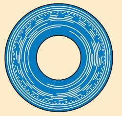
Typical absolute encoders overcome this loss of position sensing by using an elaborate pattern on the grid, Figure 3. The pattern - with eight or more pairs of light-source detectors - generates parallel pulse outputs which are available in a variety of output formats. The combination of elaborate patterns and the number of light-source detector pairs provides several unique outputs for the travel of the device.
Follow this rule for incremental encoders: the higher the line count, the greater the resolution of the device. And for absolute encoders: the greater the number of outputs, the greater the resolution of the device. Note that the cost of the encoder increases as resolution increases.
Inductive sensors - An inductive sensor is a non-contact device that measures the change in impedance (effective resistance) of a coil. The operation is similar to that of an inductive proximity switch. Alternating current flows through a coil to generate a magnetic field around the coil. An object made of ferrous metal (or non-ferrous metal at higher frequencies) disrupts the field when the object enters it. The disruption of the field causes the inductance of the coil to change.
A proximity switch reacts to a metal target when the target approaches the face of the switch. Position sensors replace the target with a core or spoiler, which is essentially the same length as the coil. The amount of overlap between the coil and the core determines the inductance of the coil; i.e. if the core is fully inserted, then the inductance is at minimum or maximum depending on the physics of operation. Conversely, when there is no overlap between coil and core, the opposite is true. The output between these limits is a linear analog signal proportional to the amount of overlap.
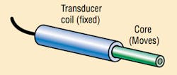
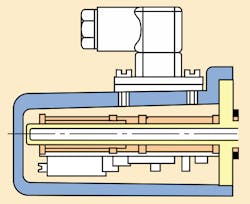
Some transducer designs are available with a moving core penetrating the inside diameter of the coil, Figure 4, while others have the core slide over the outside of the coil, Figure 5. The moving internal core design probably is best suited for retrofit applications Figures 4. The moving external core arrangement is used for cylinders which have a passage gun-drilled into the piston rod during manufacture.
All inductive position transducers use a signal conditioner or signal processor to generate the excitation current to the coil, and to detect and amplify the inductance change. The physical location of the signal processor may be on the rear of the transducer, Figure 5, or at the end of a cable between the two. The length of the cable may vary from 1 m to as much as 75 m, depending on the manufacturer. These transducers may be powered by low voltage DC to 115/230-V AC, depending on the manufacturer and model. They provide a 0 to 10-V DC or 4 to 20 mA output, which is compatible by most programmable, motion, or dedicated controllers.
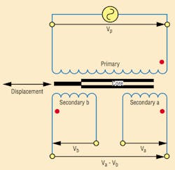
LVDTs - A linear variable-differential transformer (LVDT) is a non-contact transducer that converts linear displacement into an analog electrical output signal. (The same technology can by applied to rotational displacement in an RVDT.) LVDTs consist of primary transformer coils wound on non-magnetic cylindrical-coil forms. Two secondary transformer coils are wound on top of the primary. This coil assembly is then installed in a mechanical housing. The other major component is a ferromagnetic core moving inside the coil form, Figure 6.
In operation, the primary coil typically is excited at 5- to 8-V AC between 60 Hz and 20 kHz. The alternating current in the primary winding creates an axial magnetic flux field that is concentrated in the core. This flux is coupled to the secondary windings through the core, inducing an output voltage in each secondary winding.
When the core is centered between the two secondary windings the voltage induced in each is identical. Voltage Va induced in secondary a and voltage Vb induced in secondary b will be in phases with the excitation voltage. The output (VaVb) will be zero. The core position where the output voltage is zero is referred to as the null position.
When the core is moved in either direction from the null position, the amplitude of VaVb changes in direct proportion to the displacement. The phase relationships with the excitation also changes. In one direction, the output signal will be in phase with the excitation and 180° out of phase in the other direction. The output voltage, therefore, has two components:
- amplitude indicating the magnitude of the displacement, and
- phase relationship indicating direction of displacement.
For applications where the OEM has already installed the LVDT, such as in Figure 7, the user will only need to be concerned with connecting directly with coils. A signal conditioner, either external or internal to the transducer, will generate the excitation and provide DC voltage or current output that is proportional to displacement of the core.
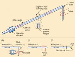
Magnetostrictive - A magnetostrictive position transducer is a non-contact device that detects the position of a magnet. The magnet moves along the length of the sensing element and is attached to the object whose position is to be determined, Figure 8 (Top).
The magnetostrictive linear displacement transducer (MLDT) relies on the basic principle of magnetostriction, which causes some ferromagnetic materials to change dimension when subjected to magnetic fields. The construction of a typical MLDT includes an electronic sensing head and a conducting wire coaxially mounted in a waveguide. The waveguide is made of a magnetostrictive material that is mounted within a protective housing made of a non-magnetic material. The waveguide is spring mounted on one end for damping. An external magnet moves along the exterior of the housing.
A current pulse is launched along the conducting wire in the waveguide. This generates a circumferential magnetic field around the waveguides as the current pulse travels down the conducting wire. When the magnetic field from the current pulse intersects with the field of the external magnet, the interaction of the fields forms a third field. This causes the waveguide to experience a minute torsional strain or twist. The strain pulse travels at ultrasonic speeds along the waveguide and into a pickup mounted in the head of the instrument.
There are different methods of sensing the torsional strain pulse. Each of the variations of strain pulse sensing detects the dynamic strain induced in the waveguide and produces a signal that is sent to the conditioning electronics for amplification and shaping, Figure 8.
The precise position of the magnet is determined from the time interval between the initiation of the current pulse and the arrival of the torsional strain pulse in the head. This time interval multiplied by the travel speed, of the strain pulse along the waveguide, indicates the position.
The output is digital in nature. The most common are start-stop pulse width modulated (PWM). These electronic circuits are either self-contained or available as a separate module. An analog conversion is readily available that generally provides 0 to10-V DC or 4 to 20 mA as an output interface. Most units use DC excitation.
MLDTs are generally available in external- and internal-mounting configurations. The external mounts usually consist of an extruded aluminum housing to protect the waveguide assembly. There are many variations of the housing and magnet assembly, but the most common is the rod and cylinder style. The rod and cylinder type has an internal magnet assembly attached to the rod and is moved as the rod is stroked. This style resembles a pneumatic cylinder and is often mistaken for one. MLDTs mount inside cylinders in a manner similar to that of the inductive transducer, illustrated in Figure 8.
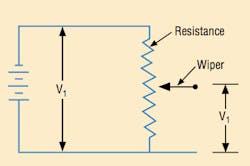
Resistive sensors - A resistive sensor, commonly called a potentiometer, uses electrical resistance as a means of measuring position. An electrical circuit is established between the two ends of the conductive strip of material, Figure 9. A constant voltage is applied across the conductive strip. A wiper moves along the strip, from which it picks up voltage. Voltage increases as the wiper moves closer to the positive end of the strip. These resistive sensors are available configured for either linear or rotary applications.
Linear versions can be mounted internally or externally to the cylinder. The rotary unit is generally mounted externally and measures angular position directly. Some rotary potentiometer measures linear position by using a spring-loaded drum and fine cable, which pays in and out with changes in position. These are called string pots and are useful for long stroke lengths.
The output of a resistive sensor is ratiometric to the voltage the user applies. Because resistive sensors are not generally provided with any form of signal conditioning electronics, the user is responsible for ensuring that appropriate electrical parameters are evaluated. These parameters include - but are not limited to - excitation voltage, power dissipation, and wiper current, as it relates to the input impedance of the controller.
Measurement error
All position transducers are electromechanical devices and are made from more than one material. For this and other reasons, they respond not only to changes in position, but to variations in temperature, shock, vibration, and excitation. The output of the transducer will likely vary if operated from one end of its specified temperature range to the other end. The electronics may also experience catastrophic failure if subjected to prolonged exposure at temperature and humidity levels beyond the manufacturer's specifications.
There are many other characteristics such as linearity, hysteresis, repeatability, etc., that help quantify the measurement accuracy of a position transducer. Other factors, are more elusive - such as packaging, configuration, materials of construction and internal design. Each of these can be appraised only on the basis of field testing and/or experience.
All of these factors must be considered, as well as the particulars of the application and the expertise of the individuals involved in making the system perform as required. The wise buyer will choose a transducer based on operating principles, specifications, price, and the reputation of the vendor.
Physical considerations
Two important considerations include the operating principle and the packaging of the transducer. Both of these principles effect size, life, maintainability, and durability. The operating principle also influences linearity, repeatability, resolution, temperature stability, maximum velocity/response time, and interface.
One operating principle compares the use of a contact to a non-contact type device. A properly installed non-contact type device will typically have less maintenance and greater longevity than a contact type device. This operating principle also determines the complexity of the signal-conducting electronics. A contact-type device, such as a resistive sensor, requires simpler electronics than a non-contact devices, and thus, is generally less expensive. Additionally, the package length is closer to the operating length of the resistance sensor.
A transducer's internal construction must be rugged enough to stand up to physical abuse. The construction of the position transducer installed in a cylinder may be dictated by the fluid media temperature or pressure. A protruding transducer can make a convenient step for maintenance personnel climbing on the equipment. Falling debris is another potential source of physical damage to the transducer or interconnect cables. Whenever possible, transducers should be accessible, but not in areas subjected to potentially damaging conditions. Internal mounting of the transducers may be the best way of protecting the device.
Other specifications
There are many design features that do not appear in published specifications that may be important over the life of the application. These design factors and technologies all have to be compared to what the user actually needs.
Transducers mounted on moving structures need to consider mounting orientation and cable length and routing. Certain locations or attitudes subject the transducer to severe vibration that can cause catastrophic failure.
External mounting is often preferred for retrofit applications because the expense of gun drilling and machining the cylinder is avoided.
Summary
It is evident that no one transducer can meet the design criteria of all applications. It is important to understand the features and benefits of each position transducer. You must also be able to interpret the specifications and how they will be affected by the particular application.
In-cylinder extensometers
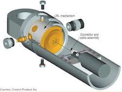
In-cylinder extensometry is a relatively new technology using a linear-to-rotary-to-linear (LRL) mechanism to translate the long stroke of a hydraulic cylinder to the relatively small motion of a short-acting sensor, such as an LVDT.
The LRL mechanism is a micrometer-like assembly, which forms the axis of a recoil spool mechanism. The spool uses a polymer-coated, stainless-steel cable to form a reliable, repeatable coupling between the piston and the sensor. Anchoring the connector to the piston causes the cable to wind or unwind from the spool as the piston rod retracts or extends, respectively.
The big advantage to this technology is ease and economy of installation - no core drilling of the piston rod is required. The assembly also offers extreme immunity to shock, vibration, and environmental factors, regardless of stroke length.
The LVDT sensor provides absolute output, and, unlike resistive sensors, it uses non-contacting technology. Developed initially for mobile equipment applications, in-cylinder extensometers fill a void in the deployment of advanced control for a wide range of machinery, including refuse trucks, excavators, agricultural and marine equipment.
This file type includes high resolution graphics and schematics when applicable.
