A Guide to Basic Components in Modern Fluid Power Systems
Today’s hydraulic and pneumatic systems are comprised of various components, enabling them to perform a range of machine functions. Greater integration of controllers, sensors and other components is also helping fluid power systems to become more intelligent by allowing them to collect more data as well as communicate with other systems.
During the National Fluid Power Association’s (NFPA) December 2023 Fluid Power Industrial Consortium (FPIC) quarterly technology conference focused on connected systems and machines, DJ O’Konek, Engineering Manager at Nott Co., outlined the components and terminology commonly associated with current fluid power systems as well as the types of data that can now be collected.
Gaining an understanding of the components and terminology associated with intelligent fluid power systems will help to ensure optimized designs and better use of their data collection capabilities.
Controllers
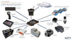
These are devices that can be programmed to make decisions based on operator input or sensor data. There is almost always a primary controller in the system which can be used for supervisory functions, edge computing or as the primary controller making most of the decisions.
In addition, smaller controllers can be integrated with individual components and communicate with the central primary controller to create a fully connected system. This is enabling the creation of creation of more compact, streamlined architectures. The advent of new, compact microcontrollers is making it easier to integrate controllers into new and existing components.
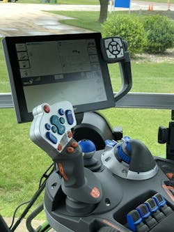
There is also a trend toward integrating primary controllers into other devices to help create more compact systems. Instead of having a touchscreen, primary controller, joystick and motor controller – all of these devices are becoming available as programmable primary controllers for the system, enabling redundancy to improve safety or consolidate system designs.
Sensors
These are the devices which detect the physical properties of a system or the environment. In a fluid power system, they can be used to detect pressure, temperature, rotation, displacement, or other attributes.
Many sensors are now equipped with J1939 (see definition below), allowing access to raw sensor data on the system’s CANbus rather than having to send it to a primary or secondary controller to be converted to CAN data. Temperature, pressure, rotary, and fluid condition monitoring sensors are examples of those available with J1939 onboard.
Cameras on a vehicle or machine are a type of sensor which can be used with fluid power systems as well. They can be used to detect objects and signal actions to take, such as applying vehicle brakes (which often use hydraulics or pneumatics) when a person is detected as part of a safety system.
READ MORE: Sensors in Fluid Power Bring a Range of Design Opportunities
Actuators
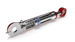
Devices which produce force in the real world, either through torque or displacement. Hydraulic cylinders, hydraulic motors, electric motors, electric linear actuators, and electrohydraulic linear actuators are all examples of these devices.
Integration of sensors and controllers with actuators allows collection of more data including speed, rotation, torque, displacement, current draw and linear force.
Pumps, Valves, Compressors
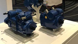
This group of components provide the fluid power to a hydraulic or pneumatic system. Examples include hydraulic pumps, pneumatic compressors, hydraulic cartridge valves and pneumatic valves.
Pressure, flow, speed, torque and actuator position are some of the data which can now be collected from these devices due to the integration of controllers and sensors.
Prime Movers
These are components which drive the hydraulic pump, pneumatic compressor or other devices within a fluid power system. Electric motors and internal combustion engines are examples of prime movers used with fluid power systems.
Onboard controllers and sensors are providing data on speed, rotation, torque, current draw, bus voltage, coolant temperature and more from these devices.
CANbus
Controller area network (CAN) is a communication system that enables communication between devices in a system.
J1939/CANopen
These are the commonly used CAN protocols used within the off-highway mobile equipment industry, a key customer segment for hydraulics and pneumatics.
J1939 is governed by SAE (Society of Automotive Engineers) and CANopen by CiA (CAN in Automation). Both are used to specify how CAN devices should communicate with other components in a machine or system.
User Interface
This is a device that allows operators to interact with a system, such as a touchscreen display, joystick, foot pedals or dial. Basically, it is any type of device that the operator can interact with to provide information to the fluid power system.
Most of these components have had J1939 integrated into them for some time.
Telematics
This is the system which collects and transmits data to the cloud for presentation, analysis, and storage. It communicates with everything connected to the CAN network.
Cellular networks are the most common method used to transmit data via the telematics system but WiFi and Bluetooth can also be used. Many manufacturers are moving telematics gateways into displays, controllers or other existing components to minimize additional componentry and wiring in systems.
READ MORE: Connecting Vehicles to the Cloud
Gateway
A device which facilitates the connection between the fluid power system and the cloud.
API
The Application Programming Interface provides a defined set of rules for how different applications talk to each other.
About the Author
Sara Jensen
Executive Editor, Power & Motion
Sara Jensen is executive editor of Power & Motion, directing expanded coverage into the modern fluid power space, as well as mechatronic and smart technologies. She has over 15 years of publishing experience. Prior to Power & Motion she spent 11 years with a trade publication for engineers of heavy-duty equipment, the last 3 of which were as the editor and brand lead. Over the course of her time in the B2B industry, Sara has gained an extensive knowledge of various heavy-duty equipment industries — including construction, agriculture, mining and on-road trucks —along with the systems and market trends which impact them such as fluid power and electronic motion control technologies.
You can follow Sara and Power & Motion via the following social media handles:
X (formerly Twitter): @TechnlgyEditor and @PowerMotionTech
LinkedIn: @SaraJensen and @Power&Motion
Facebook: @PowerMotionTech

Leaders relevant to this article:
