Designing and Troubleshooting with Screw-in Cartridge Valves
At a Glance:
- Sometimes the perfect valve has been specified for an application, but something goes wrong during installation or testing.
- Before specifying valves and other components, engineers should understand where and how they will operate.
- Here’s what engineers should know when designing or troubleshooting screw-in control valves applications, along with some case histories to illustrate why.
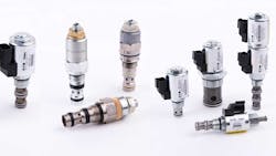
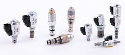
Screw-in cartridge valves (SiCVs) are widely used, but they occasionally cause problems. In some cases, the valves do not operate properly. In others, interactions between SiCVs and other components cause the problems. And sometimes the cause of problems is installation or user errors. But often the issue is a lack of comprehensive application information on the part of the engineer or designer. So, here’s what engineers should know when designing or troubleshooting SiCV applications, along with some case histories to illustrate why.
Understand the Application
To ensure that the correct and most cost-effective valve is used, OEMs must share—and system designers must push for—in-depth application information. That includes:
Pressure. Maximum system pressure is an obvious starting point, but it’s not enough. Pressures vary throughout the system—and can even be higher than maximum pressure—so engineers need to consider where the valve will be located. They should also be aware of intensification in the circuit, motors in series and gear flow dividers. There might also be shock pressures caused by machine operation. For example, digging, crushing, chopping and momentum can cause unexpected surges or spike pressures.
In one instance I personally witnessed (as with the other examples mentioned throughout this article), the valve location of a gantry crane at a port resulted in the brakes not coming on fast enough. The operators took great delight in showing me the issue; they accelerated the machine towards the end of the wharf and released the joystick. The crane kept moving towards the end of the wharf, approaching the edge and a dunking far too quickly for my liking. The solution was to mount pressure-reducing valves closer to the motors so that pressure did not have to build up along the entire hose run before the brakes were applied.
Flow. Another (perhaps obvious) application parameter needed is the system flow, which lets engineers size the valves properly. Flow varies depending on the type of actuator being used. Flow from cylinders can be multiples of the inlet flow. Flows may also be split so that smaller valves will suffice, or regenerative systems can amplify the flow.
In one case, a customer was fitting a cover to a skip truck with extendable rotary arms. The customer complained that the spool-type flow dividers we supplied were not accurate enough. When the arms reached their resting point, one bottomed out before the other by a small amount. With ±10% accuracy for this kind of product, we explained that the valves were working as they should. The customer then told us that another supplier’s product had been used and was working fine. On closer examination, we discovered that the minimum flow rating for the other valve was much higher than the flow in the system. In essence, the valve was doing nothing. To demonstrate, I took the spools out of our valve and the cover functioned in the same way as on the other supplier’s. We explained that, without the valve, or with a non-functioning valve, the flimsy framework would twist if one side of the cover gets snagged.
Environment. Imagine an olive tree shaker. To harvest the olives, the machine grabs the tree’s trunk and shakes, making olives fall onto a tarpaulin encircling the tree. Pilot check valves are mounted on the shaker cylinders, which vibrates fiercely. Many valves, including most of ours, are rated to last at least 1 million cycles, which is typical for SiCVs. Depending on the application, valves can last much longer or break down quickly. In this case, it took only two months for our valve to fail. Not good enough. As a result, the customer switched to another supplier’s valves. It also failed within a month. They tried yet another supplier’s valves and got the same results. They then called our company for help.
After some study, we determined the valve went through 1.25 million cycles per month with unknown pressure spikes. We decided to go with an older valve design with a pilot piston pushing against a poppet check. The valve, typically used in industrial applications, had been tested to 10 million cycles.
The point of this incident is that before specifying valves and other components, engineers should understand where and how they will operate. Environmental factors and ambient temperatures might be beyond the safe working limits of the valve or its electrical components. The answers to questions such as these will help design teams seriously consider safety and service life impacts:
- What is the valve’s duty cycle?
- How often does the solenoid operate?
- How frequently does the relief valve open?
- Could the valve be exposed to water, salt or acid?
- Is the environment dirty or dusty?
- Will the valve be used in dangerous areas?
- Is there a risk of fire or explosion?
- Can the valve be mistreated? For example, could it be used as a footrest for a heavy boot?
Understand the Product
Once the design team thoroughly understands the application, it can begin to narrow down the contenders and evaluate potential valves. This entails understanding the function and operation of each type of valve, as well as how it works with other circuit valves and components.
Function. Engineers must understand how each valve operates if they are to choose the best one for their design. Engineers should not be limited by the name of a valve. If they understand its operation, they can use it in brand-new ways. For instance, sequence valves can be used as a logic element, a flow compensator or a pilot-to-close valve in applications such as regenerative systems, spreaders and tool take-off circuits.
Engineers who do not completely understand a valve’s function and only look at the circuit can wind up making errors. In one case, an engineer mistakenly used standard over-center valves on bucket cylinders, causing them to bend. The engineer had assumed that relief valves in series would protect the cylinder. They didn’t. The standard valve was replaced with a part-balanced valve in which the relief remains open despite back pressure.
Understanding a valve’s operation also allows design teams to account for interaction between valves; such interactions are often why a system is not performing up to snuff. In one case, a client had four relief valves fitted in parallel in a high-flow application. Each valve fighting for flow created a loud, unsettling noise. To silence the noise, we changed the valves’ settings so that there was 50-psi between each.
Performance. Before specifying a valve, designers must understand what is expected throughout the machine’s life, the safety requirements,and the OEM standards that must be met. Important data points include the valve’s leakage, hysteresis, accuracy and response time. Some of these can change over a valve’s service life. For example, a valve’s leakage may change depending on the viscosity, oil cleanliness, erosion and whether aggressive fluids are used.
Installation and use. Sometimes the perfect valve has been specified for an application, but something goes wrong during installation or testing. Perhaps they weren’t torqued correctly or a technician did not know how to properly adjust them.
In one unfortunate example, a customer managed to bend a 20-foot-long pallet stacking cylinder. The valves had a dampening device that could be adjusted to prevent the compensator spool from moving too far. The customer saw a bit of instability and adjusted one of the dampening screws, only to close it off completely. This resulted in a container being lowered on one cylinder while the other bent like a coat hanger. We worked with the customer to ensure everyone who went near the hydraulics on this machine knew how the valves functioned and what could go wrong.
Boiling down SiCV design and troubleshooting into knowing the application and product is perhaps a vast oversimplification. Understanding the valves is easier said than done. Eaton, for example, offers 12 types of control valves. There are 177 different functions; five sizes, in most cases; and an array of pressure settings, flow settings, manual overrides, adjusters, solenoid voltages and terminations, seals, and line body options. That provides more than 200,000 options from which to choose. With so many valves, it can be difficult to understand the nuances behind all of them.
So, what’s a designer to do?
There are many ways to learn. The best way, undoubtedly, is through experience. Beyond that, attend training. Look into virtual sessions and in-person classes (the latter, if pandemic conditions allow). These courses go into great depths on the function, operation and application of each valve. Also inquire as to what materials suppliers have so you can learn on your own time. Eaton, for example, offers several articles in its SiCV catalog that explain valves.
OEMs, for their part, generally know the endgame and want the most cost-effective valves. Partner with a supplier or integrator that can help. These firms understand the intricacies of valves and will work closely with you to explore and understand the application, then develop a solution, normally in the form of a hydraulic integrated circuit (HIC).
Gone are the days when only SiCVs were considered for these applications. Suppliers have access to a broad range of hydraulic components to ensure they will likely have the right one. They can have industrial valves that are simple to incorporate given their standard mounting patterns, as well as mobile valves which can be mounted to manifolds. Filters and accumulators can be added to the package, and the manifold can be attached to the pump or motor, depending on the customer’s preference.
The keys to a successful outcome are a close partnership at every stage of the design cycle, a full understanding of all requirements upfront and the flexibility to provide the performance needed while addressing client’s preferences.
Maurice Ashmore is global chief engineer of SiCV & HIC at Eaton Corp.
About the Author
Maurice Ashmore
Global Chief Engineer of SiCV & HIC, Eaton Corp.

Leaders relevant to this article:

