In the nearly 40 years since electronic control systems first became common features of industrial machines, controls theory has necessarily evolved to keep pace with machine design. Early on, systems relied on basic start/stop and limit switches, with perhaps the added sophistication of two-speed valves. It then became possible to coordinate various parts of the system’s action, with sensors indicating various states; early microprocessors kept track of those states and issued command signals based on programmed instruction sets. As processing power and speed have increased, electronic industrial system controls are growing ever more sophisticated and becoming ever more capable.
Why Energy Transmission Makes a Difference
Electromechanical systems transmit energy to the load with solid material parts like shafts and gears. Therefore, these systems feature near instantaneous on/off capabilities, and controls are essentially unaffected by environmental or system changes, such as temperature. From a controls standpoint, these systems are stiff and linear, meaning control algorithms can be simpler. However, electromechanical systems are challenged by shock or dynamic loading, and experience mechanical wear, resulting in a finite working life before refurbishment or replacement.
Fluid power systems have tremendous power density and are significantly more tolerant of shock loading. That is due to the use of hydraulic fluid as an energy transmission media. When the system is shocked, the hydraulic fluid exhibits compressibility effects and will also transmit forces to the pipes, hoses and tanks that contain the oil in fluid power systems. Shock distribution does not typically result in permanent damage to a hydraulic system, and the system can continue to operate normally after long periods of shock loading events. As a side note, hydraulic fluid characteristics will exhibit slightly different behaviors depending on changing environmental conditions such as temperature.
Getting precise and repeatable control on a fluid power system has been a challenge historically. As processors have increased in power, what were previously theoretical control algorithms can now be implemented on real systems. Algorithms that simply could not be calculated, or could not be calculated in a short-enough time to be useful for controlling an actual machine, are now easily implemented. The capabilities of control electronics have caught up with the physical world.
Design Considerations
To reliably and precisely control a hydraulic system, it is important that the system response be as linear as possible. This means that unit changes in control output should result in consistent changes in system response. To some degree, advanced controllers can bypass this system linearity requirement through system modeling, but the linearity premise remains. If the system design is nominally linear, controllers can use straightforward algorithms on the system and provide control output to produce exactly the desired response with minimal error.
There are design best practices that can help achieve a highly controllable system. What can be challenging about controlling hydraulic systems is the compressibility of the oil and the flexibility of hydraulic hose. Therefore, minimizing excess oil volume between the powered side of the cylinder and the servo valve increases the system’s stiffness. It is best to mount the valve directly on the cylinder; if that isn’t possible, using hard pipe for plumbing instead of flexible hose between the valve and cylinder increases stiffness and, therefore, controllability. Making sure the system’s static friction is not high allows the control output to be efficient and effective, and enables more precise system control.
Using high-resolution feedback sensors gives the best information for control. An advanced controller will not just use the high-resolution position feedback for control but can also derive velocity and acceleration of the moving axis, using those values in the control algorithm.
Designers should not just consider the maximum desired system velocity and design and size system components for that value. If a simple PID controller is being used, they should consider how fast the system must accelerate or decelerate, and make sure the frequency of this acceleration is less than or equal to one fourth of the natural frequency (ωN) of the system. Figure 1 shows an example of system response where the frequency of acceleration (FoA) is just half the system ωN.
Figure 2 shows the same motion profile, but with a ratio of FoA to ωN of exactly 4:1, resulting in actual motion that much more closely matches the target. The 4-to-1 frequency ratio applies to the use of standard controllers; motion controllers with more advanced control algorithms can achieve good system control at ratios of about 2-2.5 to 1. The result is the ability to use smaller cylinders, smaller valves and smaller power units—and therefore, achieving smaller system component costs.
Sophisticated Controls
PID controls must have some amount of error between the desired (target) output and the actual system response. Therefore, the response of a system controlled by PID terms alone slightly lags the target. If velocity and acceleration feed-forward control factors are added to the control algorithm, the result is excellent tracking with a lag-free control output generated based on the target position, velocity and acceleration.
As the cylinder moves along the calculated target trajectory, the control system can accurately anticipate system response and achieve final position with no perceptible overshoot. Getting this result requires adding enhancements to the basic PID algorithm. Figures 3 and 4 are plots of short, quick moves, illustrating the difference between a basic PID control algorithm and a PID with velocity and acceleration feed-forward terms added.
Processing power is now at the point where implementing other advanced control algorithms for controlling hydraulic systems is not only possible, but realistic for everyday usage. That power opens up new realms of system control. As long as the control system receives regular, electronically clean, high-resolution reports on the motion system’s position—and can control the hydraulics through responsive, reasonably linear servo-quality valves—fast response and repeatable high-accuracy moves are possible.
The above discussion suggests the benefits of adding feed-forward terms to the control algorithm, but a second derivative term (D2) can also be added to the PID which results in a PID + D2 + feed-forwards. With the addition of the D2 term to the basic PID, the controller can now fully compensate for the compressibility of the oil in a large volume system or compensate for the flexibility of hose in a sub-optimal system design. Of course, it’s always desirable to design the system to minimize hose between the valve and actuator and other contributors to 2nd order system effects.
What’s the next step in advanced control algorithms? The next step is the use of observers and mathematical system models to augment the quality of the feedback that the system is using for control. An observer is an algorithm that estimates the state of a system, based on the inputs and “observing” the output. A good system model that is used with an observer can increase the quality of the position feedback, and allow a system to ride through short durations of feedback failure.
This same model/observer combination can not only significantly improve the quality of the velocity and acceleration feedback, but can also reduce the phase delay of this information to zero. From a control standpoint, this is a very big deal.
Solving Real-World Problems
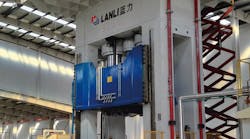
An automotive parts manufacturer uses a four-corner press produce tight-tolerance auto body panels (Fig. 5). At 30 ft (~10 m) in height, the press is very tall. The servo valves controlling the four hydraulic rams were mounted at floor level, while the cylinders they were controlling were up higher on the press.
An advanced motion controller was able to account for the non-linearities and lag in system response resulting from the fact that the system had extra oil between the valve and cylinder, as well as flexible hose which expanded under pressure. Once the system was characterized, the controller was programmed to correctly anticipate system response, and smoothly position the die cushion and maintain a constant force on the workpiece. The resulting press produces parts to a high degree of accuracy and moves smoothly between pressing and retracting with no oscillation. Prior to setup, the press would oscillate, shaking the building where it was installed!
To study hydraulic control problems like this in more detail, Delta Computer Systems’ engineers built a hydraulic lab apparatus which was intentionally designed to be difficult to control. It features a sizable mass on a long, thin cylinder—a classically underdamped system that is prone to oscillation. To demonstrate and test different system challenges, the oil can be routed from the valve to the cylinder either through short runs of hard pipe, or long runs of flexible hose. These paths are selected with manual ball valves. This system is intentionally difficult to control and breaks a few “best practice” principles.
With Delta’s RMC75 motion controller, the system is tuned easily using the company’s RMCTools Tuning Wizard. The controller characterizes the system, and applies the correct gains and generates a smooth motion profile to move the system with nearly zero overshoot or oscillation.
Freedom for Designers
Advances in processing power and feedback resolution have opened up new opportunities for system design. As power and speed increase, controls engineers are able to move from theories and models to actually implementing these ideas in physical control hardware, which benefits designers and end-users alike. These advances enable industrial controllers that can be pushed to solve previous practically impossible control problems. This opens up new possibilities to apply fluid power to applications that require power, precision and speed.
This article appeared in Machine Design.


