Several different technologies can be used to store energy in accumulators: weighted pistons, bladders (or diaphragms), springs and the commonly used hydro-pneumatics. Accumulators use that energy to keep system pressure relatively constant or to put oil under pressure for low duty cycle actuators. In a previous article, I mentioned that hydro-pneumatic accumulators should be pre-charged to about 90% of the system pressure, typically with nitrogen. This ensures the accumulator contains mostly nitrogen and just enough oil to keep the accumulator from being completely empty. While calculating the pre-charge pressure was a difficult problem, figuring out how big the accumulator must be is a challenge.
To calculate the right size for the accumulator, the engineer must know how much the volume of oil or gas changes during operation. Oil is simultaneously being removed by flow through servo valves and added by a pump. If the pump could instantly supply the amount of oil being used, there would be no need for the accumulator.
Unfortunately, pressure compensated pumps do not respond to pressure changes quickly enough, so oil comes from the accumulator at the start of every motion. While the oil comes from the accumulator, the oil volume decreases and the gas volume increases, thus reducing pressure until the pump catches up with demand.
Estimating the pump flow can be done by calculating the total flow required per cycle, then dividing by the time. But that assumes the pump provides constant flow for constant motion profiles. This is possible when using a fixed displacement pump with its speed controlled by a motion controller; the controller can calculate the average flow for a cycle. A pressure compensated pump’s flow varies depending on the pressure and does not provide full flow until the pressure has dropped enough that the swash plate is at full stroke.
Problems arise when pressure must drop more than 10% before the pump can supply the average flow for the cycle. So, it is best to have pressure compensated pumps with narrow pressure bands. Normally pressure bands cannot be changed because they are determined by the spring constant of the spring in the pressure compensator. Thus, it can only be changed by the manufacturer.
Calculating the instantaneous demand requires knowing the motion profile as a function of time. This includes acceleration and deceleration rates, maximum velocity and even the dwell times (if any) at the end of extending and retracting. Dwell times are important because they let the pump catch up with the oil demand. In general, longer dwell times let engineers get by using smaller pumps.
The required flow is estimated by multiplying the extend velocity by the area of the cylinder’s bore; when the cylinder is retracting the required flow is the result of multiplying the retract velocity by the area of the piston’s rod side.
The total amount of oil used is easy to calculate—the tricky part is calculating the motion profile as a function of time. The calculations can be done using a spreadsheet, but they can be awkward because as the profile changes, the large number of rows and the formulas in each row makes it easy to make an error.
A motion controller, however, is perfect for generating motion profiles. Engineers can then multiply by the correct areas and sum the changes to the oil flow and calculate the oil-flow change over the cycle. The motion controller can also simulate pump flow and plot all the data.
Most importantly , engineers need to how much oil is being added, how much is removed and a running total. Then they can determine the maximum and minimum oil volumes and the difference between them. This volume is multiplied by 12.8 to get the minimum volume for the accumulator; a little more should be added for safety, so multiplying oil-volume difference by 13.8 to 15 will yield an accumulator size that will always have a little oil in it.
Simulation programs can simplify accumulator sizing, but they take time to write or are expensive to buy.
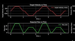
Below are plots from a simulation program:
This plot is a motion profile that moves 300 mm in one second and then dwells for 0.1 sec. before moving back.
The second plot shows oil flow as a function of time. Notice the flow is greater while extending due to the larger surface area of the piston’s cap side of the piston relative to its rod side.
The third plot shows the net oil changing over time. Notice the oil volume drops more when the rod extends than when it retracts. Oil volume increases during dwell times and when moving slow.
The fourth plot shows the pressure changing over time. System pressure is 10 MPa (100 bar). The pressure drop is limited to 10%.
The final plot shows the volume of oil in an accumulator with known size. The changes are identical to the third plot but actual volumes are known instead of just the changes. The calculated accumulator was to be 3.74 liters, but it is doubtful one that exact size can be found, so a five-liter accumulator will be used. This will result in the pressure dropping a little less than 10% and having a little more oil in the accumulator during the low points. Also, the minimum pump size only needs to be 25.50 liters per min even though the peak flow is 53 liters per minute. The accumulator can save money by reducing the need for larger pumps.
To size an accumulator for a hydraulic servo system, it makes sense instead to use a motion controller to help calculate the accumulator size. Finally, whatever method is used to compute the accumulator, chances are that exact accumulator size is not available, so the next size bigger must be used.
Peter Nachtwey is president of Delta Computer Systems.


