Accumulators add functionality to hydraulic circuits
This file type includes high resolution graphics and schematics when applicapable.
Hydraulic accumulators are one of the most underutilized tools in the fluid-power chest, which is unfortunate, because they provide myriad advantages to a hydraulic system. Accumulators are often misunderstood, especially as it relates to troubleshooting, but the principles of their operation are straightforward, even if the mathematics used in their specification is not everyone’s cup of tea.
Accumulators are available in two groups, mechanical and hydropneumatic. Mechanical accumulators can be loaded with either a spring or with a mass, although both are uncommon. Spring-loaded accumulators are of the piston type and installed with a spring opposed to the oil side. Just as with compressed gas, the amount of spring compression has an effect on the level of output, as more potential energy is lost as the piston moves toward the outlet port and energy is depleted.
Weight-loaded accumulators are vertically mounted and are piston-type as well, but with a large mass using gravity to pressurize fluid rather than a compressed spring or gas. Because mechanical accumulators are rarely applied, we can leave them out of the discussion, except to say a weight-loaded accumulator is the only type able to provide undiminished pressure throughout the entire length of its stroke, as gravity remains constant the entire distance of piston travel.
Bladder-type accumulators
Hydropneumatic accumulators contain both a dry side (containing compressed gas, usually nitrogen) and a wet side, containing hydraulic liquid. The dry side of the accumulator is filled with the gas to a prescribed pressure, known as the precharge, based on system requirements. Because hydraulic systems perform poorly when gases the hydraulic fluid, some form of separation is required in accumulators to prevent the mixing of fluids; bladders, diaphragms, and pistons are most common.
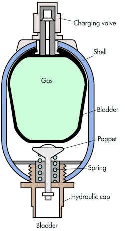
Bladder accumulators, Figure 1, are the most common form and use a synthetic rubber, such as Nitrile, to contain the nitrogen gas precharge. The bladder is installed inside a high-pressure-capacity sealed cylinder with hemispherical caps at either end. The ideal mounting position of bladder accumulators is with the liquid port downward and the gas port upward. When a bladder accumulator is charged, its bladder fills most of the void inside the shell, and a poppet valve at the oil port prevents the bladder from extruding out the bottom. Bladder accumulators are commonly available in a wide range of sizes, from 1⁄4 to 15 gal, depending on the range the manufacturer offers.
As a bladder accumulator fills with pressurized hydraulic fluid, the nitrogen-charged bladder compresses, storing hydraulic energy equal to the volume of fluid taken in factored with the pressure of the precharge. As the fluid is discharged when downstream hydraulic pressure drops, the bladder re-expands as it pushes the oil out. The vertical mounting position will help prevent uneven wear of the bladder as the accumulator cycles, and also help avoid odd occurrences of trapped fluid or early poppet closing. That being said, a bladder accumulator will survive longer in any position, including horizontally, if fluid contamination is well-controlled.
Bladder accumulators are easily repaired, and fortunately, the major players in the accumulator game offer interchangeable rebuild kits for common accumulator sizes. The most frequently chosen bladder accumulators are bottom repairable, although top repairable are offered as well. Top-repairable accumulators are useful for installation on machines with complex plumbing or difficult mounting location, as they allow the accumulator to be repaired while remaining installed on the machine. Bottom-repairable accumulators need to be removed from the machine for repairing.
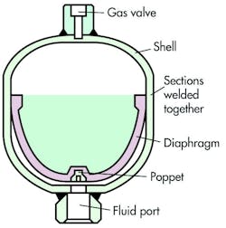
Diaphragm accumulators use the same type of synthetic rubber as bladder accumulators, but instead of the balloon shape, they are just a membrane separating the top and bottom halves of the shell, Figure 2. Diaphragm accumulators are either the welded non-repairable type or the threaded repairable type. The welded type has a diaphragm bonded in the middle to separate the gas and liquid sides, and due to the nature of their construction, they are capable of medium pressure, typically not more than 5000 psi.
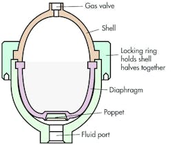
Threaded bladder accumulators, Figure 3, have a couple of advantages over the welded type, although they tend to cost more than the latter. Their threaded construction compresses the diaphragm between the top and bottom shell to hold it fast, enabling higher pressure capacity, some able to achieve 10,000 psi. The other advantage, of course, is that the diaphragm can be replaced by unscrewing the two halves. Both types of diaphragm accumulators are not typically large, ranging from only a few cubic inches of volume up to around 1 gal.
Piston-type accumulators
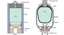
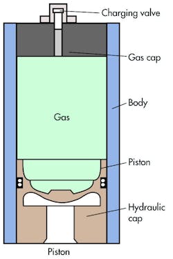
Piston accumulators, Figure 4, are similar to a rodless hydraulic cylinder capped at both ends. They include a machined steel tube with threaded caps at both ends, one cap drilled for the oil port and the other for the gas port. Some piston accumulators may be welded at one extremity, with the other side threaded for repair work. Regardless of construction, a freely sliding piston will separate the opposing fluids.
Piston accumulators are generally mounted with the oil port downward and the gas port upward. However, just like bladder accumulators, they will last longer on their side if fluid conditioning is optimal. This is especially important considering that contamination could rest on the bottom of the tube of the accumulator while the piston cycles back and forth across the particles. Although strangely available in the non-repairable type, piston accumulators are quite easily repaired, especially if no uneven wear is observed on the barrel.
What changes little among accumulator types is how they function and perform in hydraulic applications. Most circuits use the accumulator for energy storage, similar to a battery or capacitor, although some systems use them to dampen pressure spikes or pulsations.
Because the bulk modulus of hydraulic fluid is very high, it compresses little under pressure, preventing the storage of any usable amounts of potential energy. Nitrogen, on the other hand, is highly compressible, and as such, can expand to its original volume after compression occurs. Although not a perfectly efficient process, because some energy is lost to heat, the energy put into an accumulator can be called upon when demanded. This type of hydraulic energy storage can provide a few benefits to a hydraulic machine designer.
Accumulator versatility
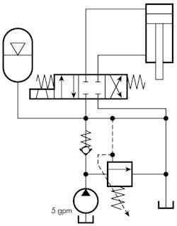
One benefit of hydraulic accumulators is to supplement pump flow, Figure 5. In some hydraulic applications, a short burst of high flow is required, such as in a punch press. To achieve the desired cycle speed in the punching operation, 20 gpm is required over 10 seconds. However, the pump output is just 5 gpm, so this velocity is not achievable on raw pump power alone. For the 50 seconds of dwell time between press functions, we can use the 5 gpm pump output to store energy in the accumulator, so the system is once again prepared for high-velocity press function. Accumulators used to supplement pump flow save the energy required to idle a larger pump, and also allow the use of a smaller pump to achieve a higher demand.
This same circuit could be used for intermittent actuator control, such as a clamp, which uses less than the 20 gpm indicated. If our clamp cylinder only requires 5 gpm once every minute for five seconds of clamp function, then the power unit could be controlled via a pressure switch plumbed downstream of the check valve. The energy in the accumulator would be enough for a few clamp functions before the capacity is depleted, which would result in the switch turning the power unit back on until the switch once again reads full pressure, and subsequently turns the unit back off. A third use of the circuit in Figure 5 is to hold pressure at an actuator. The clamp could be a maintained function with the directional valve left activated while the accumulator makes up for any leakage or decay within the components in the circuit.
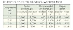
Accumulators are sized for energy storage applications based on the amount of flow required to be supplemented and the difference between the maximum work pressure and the lowest system pressure. Additionally, the compression ratio of the accumulator itself must be factored into the equation, which describes the recommended highest ratio between minimum and maximum operation of the accumulator. A higher compression ratio allows for higher volume of stored fluid, and typically piston accumulators outpace their bladder companions in this regard.
The table shows an example using 10-gal bladder and piston accumulators, and their relationship with compression ratio, working pressures, and required precharge. Optimal precharge is typically 80% of minimum working pressure, because anything too high will prevent the accumulator from being fully filled, and too low will not allow much energy to be stored. The higher the difference between maximum and minimum pressure also allows for higher energy capacity, as a drop of 5000 to 1000 PSI from the accumulator will provide more volume than a drop of 5000 to 4000 PSI, for example.
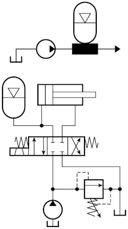
The second circuit of Figure 6 depicts an example of an accumulator used to absorb pressure spikes, such as cushion on rock-crusher rollers. Any pressure spike caused by load-induced pressure will be absorbed by the accumulator. A relief valve could be used in the same circuit, but it would direct fluid away from the cap end of the cylinder, and then would no longer return to its starting position as it would with the accumulator.
Don’t forget safety
Consider safety obligations when working with hydraulic accumulators, both in their setup and maintenance. When charging accumulators, be conscious of the potential nitrogen missile you’re working with and take care when handling the cylinders. Also ensure your charging apparatus is in good working order and of the appropriate style; there are dozens of different charge heads on the market. Finally, ensure the hydraulic energy is depleted from the accumulator before servicing, which is typically done with accumulator safety valves or ball valves. Stored energy can be expelled rapidly, causing damage or bodily harm if released in the wrong way.
Josh Cosford is a designer and Certified Fluid Power Hydraulic Specialist at The Fluid Power House, Cambridge, Ontario, Canada. For more information, visit www.fluidpowerhouse.com.
