Hydraulic-Electric Analogies: Capacitors and Accumulators, Part 2
This article is the latest in Jack Johnson's series on Hydaulic-Electric Analogies. See the "Related" articles list below for previous articles in the series.
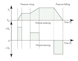
Let’s examine what happens in an accumulator as the pressure changes, which is almost always the case in hydraulic circuits. The accumulator handles molecules of fluid much like the way a capacitor handles positive electrical charges. Since the hydraulic pressure in this assessment always exceeds the gas pre-charge pressure, the accumulator operates in its active region. As the pressure increases—say just as it reaches and starts to exceed the pre-charge pressure—some volume of hydraulic fluid is pushed into the accumulator.
If we’re considering a piston-type accumulator, the piston moves an amount commensurate with the incoming volume of liquid, further compressing the gas. Increasing the pressure will force even more fluid into the accumulator. Therefore, the pressure rises with each new volume of hydraulic fluid, or conversely, a new volume of fluid enters the accumulator with each new pressure increase.
Furthermore, each new pressure increase requires a smaller volume of fluid. The ultimate limit is reached when the volume of hydraulic fluid entering the accumulator equals the original volume. To reach this limit, the gas side would be compressed to the point of occupying zero volume; however, this would require an infinite amount of pressure—an unrealistic level.
A practical limit, on the other hand, is based on the pressure rating of the accumulator and/or the pressure ratings of other circuit components. The net effect is that an increasing pressure results in a volume of fluid entering the accumulator and in turn reducing the volume occupied by the compressible gas. When the pressure is reduced, hydraulic volume leaves the accumulator. Thus, flow and pressure are related to the rate at which the pressure changes. When the pressure is constant, no hydraulic fluid enters or leaves, so the flow rate is zero.
Figure 21 illustrates the idea behind this discussion. The wave shapes are approximate, but reasonably close to what one might observe with an oscilloscope and the appropriate sensors.
If one views the electrical charged particles in a manner similar to molecules of oil in the accumulator, then the analogies between capacitors and accumulators is quite good (though it requires a bit more imagination). In reality, absolutely nothing can be seen in the charging of the capacitor. In the accumulator, it’s not difficult to imagine the piston or accumulator moving as the hydraulic charge rises and falls. Capacitors require more faith.
This file type includes high resolution graphics and schematics when applicable.
Charging capacitors and accumulators
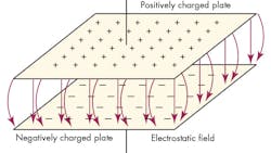
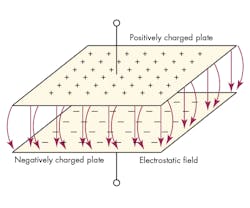
When a capacitor is charged, it means that a separation of charges exists on its two respective plates. Some force figuratively speaking, reaches into, say, the upper plate and pulls electrons away from their parent atoms, and then deposits the electrons on the lower plate (Fig. 22). This leaves the upper plate positively charged because there’s a shortage of electrons (the parent atoms), while the lower plate has a negative charge caused by an excess of negative charges. Due to the charge separation, an electrostatic field exists in the space (dielectric material) between the plates.
By convention, the electric field, indicated by the arrows, begins on the positive charges and ends on the negative charges. If one were to connect the two leads of a voltmeter to the capacitor’s two leads, there would be a potential difference, i.e., a voltage. We have no way of knowing how much voltage, though, without more information. It could be one or two volts, or it could be several thousand. However, it’s not important at this point in the discussion.
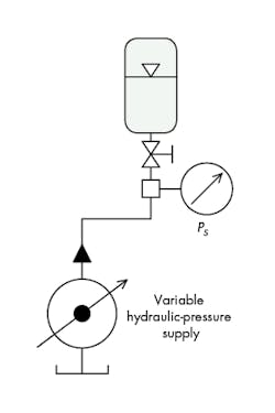
Analogously, if an accumulator was charged up with a hydraulic power supply, a measurable pressure would reside at the inlet/outlet hydraulic port. Indeed, some source of pressure had to be used to build up the gas pre-charge. Then, some hydraulic power source had to generate the pressure that forced all of those hydraulic-fluid molecules into the inlet/outlet port. The hydraulic source that put the hydraulic charge into the accumulator was a pump of some kind. Without allowing any leakage out of the hydraulic port, that pressure will stay locked inside the accumulator due to compression of the gas. The gas serves as a pneumatic spring. The gas has energy stored in it by virtue of its compression.
If the hydraulic port suddenly opens, the hydraulic fluid would spurt out, possibly in an explosive manner, spewing hydraulic fluid in whatever direction the throat was pointed. What means was used to provide the hydraulic charge? We cannot reach into the reservoir and cram the fluid molecules into the accumulator in a literal sense. Rather, the hydraulic charge results from connecting it to a hydraulic pump. The pump would have placed the hydraulic charge in the accumulator.
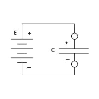
The same scenario holds true with the capacitor. Of course, we can “reach into a plate,” pull out electrically charged particles, and “deposit them on the other plate” only in a figurative or metaphoric way. The normal way is to transfer charges from one plate to the other with a battery or other dc power supply (Fig. 23).
The charged capacitor can be removed from the charging circuit and the charge will remain because of the energy stored in the electrostatic field between the plates. In time, the charge will leak off because the dielectric material isn’t a prefect insulator. Charge retention time depends on the amount of capacitance and the quality of the insulating properties in the dielectric separator.
In the picofarad range, leakage discharge is essentially instantaneous. In the tens or hundreds of microfarads, charge retention may be measured in hours. If the charge voltage is high enough, and if a human being touches both capacitor leads at the same time, an electrical shock can result. Rapid capacitor discharge can be achieved by merely connecting (shorting) the leads together, but the current can be instantaneously extremely high, damaging the capacitor.
Charge retention in the accumulator
Similar charge retention occurs in accumulators. If the accumulator is charged and its hydraulic path blocked (Fig. 24), it can be removed from its charging circuit. Thus, energy stored in the compressed gas will be retained. That energy can be used elsewhere at some other time.
This type of situation occurs in some large engine starting circuits employed in hydraulic motors. The accumulator is charged during normal engine operation and later discharged through the starter motor at engine-start time. If a system has substantial time between their charging and eventual discharge, the pre-charge gas will often have a different temperature for the pre-charge gas. If the discharge temperature is lower than the hydraulic charging pressure at charging time, the discharge pressure will be lower, creating the appearance that the accumulator has leaked. It in fact did not leak, but thermal energy passed through the accumulator housing and reduced the internal energy as a result of apparent leakage.
However, accumulators that retain their charge after machine shutdown can be dangerous to maintenance workers. Opening a circuit containing a hydraulically charged accumulator is the same as opening a functioning hydraulic circuit, and could result in serious personal injury or even death. Most circuits with accumulators are required to automatically dump the hydraulic charge when the machine goes into shutdown. The context here is the difference between the gas pre-charge and in-use hydraulic charge. The gas pre-charge need not be released at machine shutdown because the piston or the anti-extrude poppet in bladder types offer personnel protection internal to the accumulator.
If the gas-charging valve or hydraulic valve should leak, the accumulator will lose its charge, much like capacitors. An external gas connection on a piston accumulator like that shown in last month’s “Hydraulic-Electric Analogies: Capacitors and Accumulators, Part 1” (Fig. 18 in the article) can be used to increase capacitance. The new capacitance is limited only by the volume of the external gas container. The accumulator’s ability to react quickly to sudden demands for hydraulic flow is limited by any restrictions between the external gas container and the accumulator.
There’s no real analogy to the accumulator’s ability to conduct hydraulically whenever the external hydraulic pressure exceeds the gas pre-charge pressure. The phenomenon is more complex than any known, basic electronic gadgets.
This file type includes high resolution graphics and schematics when applicable.
