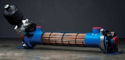
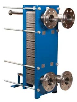
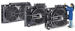
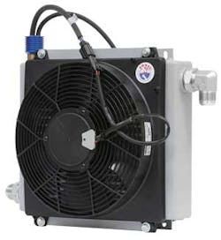
This file type includes high-resolution graphics and schematics when applicable.
Hydraulic systems can use either of two methods of load control: the energy-loss method, in which flow to the actuator is set by valving, or the volume-control method, in which the stroke of a variable-displacement pump sets the rate at which fluid flows to the actuator. Although systems using variable-displacement pumps inherently are more efficient, they are more costly and cannot react as quickly as systems using servo or proportional valves operating from a constant pressure source.
Most industrial hydraulic systems are designed using the energy-loss method. Such systems cost less to build and are more responsive because system energy is immediately available. But because of the inherent poor efficiency of these systems, energy lost as heat can exceed that of the mechanical power produced by the system. For example, even well-designed electrohydraulic servovalve or proportional-valve systems may convert 60% to 80% of input horsepower to heat. Well-designed nonservosystems can produce heat losses of only 20 to 30%.
Some hydraulic-system heat is desirable to bring fluid up to operating temperature. Cold hydraulic oil has a higher viscosity than warm oil. So maintaining an operating temperature of 100°F would cause sluggish operation and excessive pressure drop in a system designed to operate at 140°F. When a system begins operation on a cold winter morning, for example, the oil should be allowed to warm until it reaches a temperature where heat is generated at the same rate as system heat radiating into the atmosphere or other cooling medium.
If heat generation exceeds the radiation rate, the excess heat can cook the oil, start oil decomposition, form varnish on system component surfaces, and begin to deteriorate system seals. Excess heat sooner or later spells trouble for any hydraulic system. Too much heat breaks down oil, damages seals and bearings, and increases wear on pumps and other components. The solution to these problems is the inclusion of a properly sized heat exchanger as a system component.
Thermodynamics
Heat is a form of energy that migrates from one region to another when a temperature difference (gradient) exists between the regions. Heat naturally flows from the hotter region to the cooler one. The rate of heat transfer is important in determining how much can be removed from a system within a given time frame. As long as it has a higher heat-transfer rate, a physically smaller heat exchanger can remove heat from a system faster than one that is much larger.
The defining equation for any heat exchanger is:
q = U × A × ∆T
where q = heat-transfer rate, Btu/hr; U = overall heat-transfer coefficient, Btu/hr-ft2-°F; A = heat-transfer surface area, ft2; and ∆T is the fluid-temperature difference, °F.
These three factors take varying forms depending on the particular design of heat exchanger and the application involved. Inspecting the equation reveals that increasing any factor on the right increases heat-transfer rate in direct proportion. Doubling the surface area in contact with the heated fluid doubles the heat transfer rate. Increasing temperature difference between the hydraulic oil and the coolant by 50% increases the heat-transfer rate by 50%.
But if natural convection cannot remove enough generated heat, a heat exchanger must be installed to control system
temperature. The heat exchanger uses forced convection to remove heat. Another mode of heat transmission, radiation, may often occur, but its effect is small and usually can be ignored. Generally, a heat exchanger is necessary for a hydraulic system if:
- a specific oil temperature limitation is necessary to stabilize oil viscosity
- cycle dwell time is a major portion of the total duty cycle, especially in systems with fixed-displacement pumps, and
- there is a history of problems from hot oil, or shortened oil or seal life.
Heat-transfer mechanisms
The heat-transfer coefficient, U, is composed of several mechanisms. The first is the convective heat transfer from the hot fluid to the wall separating it from the cold fluid or air. This can be called the hot-fluid thermal resistance, which depends primarily on physical and thermal fluid properties. Turbulent flow and high velocity improve the heat-transfer rate.
The second mechanism is thermal conductance through the tube wall. Most heat-exchanger tubes are built from copper or similar materials that exhibit high thermal conductivity.
The third mechanism is the convection of heat from the tube wall to the cooler fluid in the tube. This mechanism acts in much the same manner as the hot-fluid thermal resistance. Use of multipass flow patterns takes advantage of the fluid velocity and turbulence for increased U values.
Other conditions that influence heat-transfer rates are fouling factors that may occur on both sides of the tubes over a period of time. When a flowing-fluid system deposits material or scale on boundary walls, they become fouled. This layer of scale:
- acts as an insulator
- increases effective fluid-film thickness, and
- reduces fluid velocity distribution near the tube wall.
As the scale thickens, heat-transfer rate decreases accordingly. Mechanical or chemical cleaning, or both, may be necessary to remove the scale when excessive deposits degrade heat exchanger efficiency.
