Download this article as a .PDF
Given the many risks of excess heat in a hydraulic system—such as fluid decomposition, increased wear on system components, damage to seals and bearings, etc.—the need for an effective heat exchanger is often an essential consideration. Smaller hydraulic systems with low operating temperatures may be able to rely on natural convection, but when that doesn’t provide sufficient cooling, a heat exchanger must be installed. You can also assume a heat exchanger is needed when a specific oil temperature is required to stabilize hydraulic fluid viscosity, or when equipment has a history of hot oil problems, such as shortened seal life or frequent oil breakdown.
Whether you work with mobile or industrial hydraulic systems, hot fluid is a concern. A properly sized heat exchanger in any equipment can save time, money, and repair headaches.
Choosing the Right Heat Exchanger
So how do you determine which heat exchanger is best for a particular application? As with most design challenges, the answer is, “It depends.”
There are many factors to consider and a wide range of heat exchangers, with certain benefits to each kind. The choice of a heat exchanger generally ties directly back to the type of system to be cooled. This means you must take into account such vital parameters as heat load, available space, environmental conditions, power source, noise, operating costs, and so on.
Accurately defining hydraulic cooling needs can be confusing because actual heat generation often varies as a machine goes through different cycles, and because ambient temperatures or other environmental factors can affect system heat levels. When considering application and sizing of heat exchangers, the ideal operating temperature of the hydraulic fluid and the time it takes to arrive at that temperature must be used.
Whether it’s a new design or a retrofit, it’s hard to pick the right heat exchanger without identifying the challenges and doing all the calculations. Fortunately, most heat exchanger manufacturers offer software to help you determine the best fit for each application. For example, Parker Hannifin provides online sizing calculators and other interactive resources where you can plug in specifications to get a better idea of what exactly is needed for water oil coolers or air oil coolers.
When working with a manufacturer to select a heat exchanger, you’ll need to provide the following information:
- Oil heat load in BTU/hr
- Oil flow in gpm
- Maximum required oil temperature
- Maximum ambient air temperature during operation
- Environmental contaminants that can affect the system
- Maximum allowable pressure drop
If the heat exchanger is water cooled, you also need to know the cooling water inlet temperature and flow rate. Most manufacturers’ literature includes examples, steps, and simplified equations to help size heat exchangers properly.
Once the heat load parameters and other key influencing factors are defined, the next steps in the decision-making process include the choice of an air-cooled or water-cooled heat exchanger.
Air-Cooled Heat Exchangers
When no water source is available, or the choice is to remove heat from the oil via the surrounding air, an air oil cooler is used to convect heat (Fig. 1). Hot oil passes through the tubes of these heat exchangers, and turbulators help break up laminar flow to promote efficient heat transfer from the fluid to the tube wall. The tube metals also have high thermal conductivity.
1. Air Oil Coolers use surrounding air to remove excess heat. Specially designed fins promote turbulent air flow to improve heat transfer capability.
There are two types of construction for the cores utilized on air oil coolers Tube-and-fin construction consists of round or oval tubes and an array of external fins. This design is lightweight and offers low pressure drop. The tubes are typically welded aluminum, and they have thin walls, making them more susceptible to damage from extreme pressures and any external debris that could be encountered in the application.
Bar-and-plate construction (Fig. 2) is characterized by its compact and efficient design. It provides more cooling per cubic inch than tube-and-fin units. The basic construction consists of finned chambers separated by flat plates which route fluids through alternating hot and cold passages. This design results in a type of honeycomb structure that offers high resistance to vibration and shock. The core usually is fabricated from aluminum, but regardless of the materials of construction, the core is furnace brazed in a controlled atmosphere or high vacuum.
2. Bar-and-plate heat exchangers consist of finned chambers separated by flat plates that route fluid through alternating hot and cold passages. Heat is transferred via fins in the passageways, through the separator plate, and into the cold fluids via fin once again.
Another reason for using bar-and-plate is that design flexibility is much greater than the tube-and-fin type. Finned passage sizes are easily varied by changing fin type, height, and density. A bar-and-plate heat exchanger size can be customized to fit a particular envelop. Heat exchanger manufacturers offer many different motor configurations, voltages, and displacements, depending on the application requirements. Mobile equipment uses either hydraulic-driven or dc electric fan motors. Industrial equipment and HPUs have ac electric motors connected to the fans and pull air through the cooler core.
Water-Cooled Heat Exchangers
When the choice is to remove the heat from the oil via a second fluid (typically water), a water oil cooler is used. Shell-and-tube heat exchangers have been the industry mainstay for well over 50 years. Recently, however, new designs have been developed to increase effectiveness and provide equivalent heat transfer surface in a smaller envelope, yet reduce cost.
Shell-and-tube heat exchangers have an outer flanged shell with end bonnets appropriately sealed to the shell ends. A precise pattern of tubing within the shell runs the length of the shell and terminates in end plates. Tube ends are fastened to the end plates, which seal each end of the shell. Cool water flows inside the tubes, and hot hydraulic oil flows around the tubes within the shell. The tubes run through a number of baffle plates that provide structural rigidity and create a maze through which the hot fluid must flow. This pattern enhances heat transfer by forcing the hot fluid to flow perpendicular to the tubes and promoting laminar flow.
A high efficiency shell-and-tube design adds a number of fins to the external sides of tubes. These fins provide more surface area and improve the heat transfer coefficient, thereby reducing the size of the heat exchanger over standard shell-and-tube configurations. However, because of the increased internal heat transfer surface area, pressure drop is higher than in the older versions.
Newer Designs
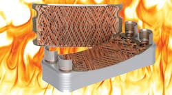
Another newer heat exchanger design is the brazed-plate type. With a brazed-plate heat exchanger (Fig. 3), the heat-transfer surface consists of a series of stainless steel plates, each stamped with a corrugated pattern designed for a combination of high strength, efficiency, and fouling resistance. The number and design of the plates vary according to the desired heat transfer capacity. The plates are stacked together with thin sheets of copper or nickel between each plate. The plate pack, end plates, and connections are brazed in a vacuum furnace to secure the plates together at the edges and at all contact points. Inlet and outlet connections are available in a number of different styles.
3. This cutaway shows the cooling elements of the Parker OAW Brazed-Plate heat exchanger.
The brazed-plate heat exchanger is compact, rugged, and provides high heat transfer capability. A brazed-plate heat exchanger holds about one-eighth the liquid volume of a thermally comparable shell-and-tube counterpart. Stainless steel construction of the brazed-plate design allows flow velocities as high as 20 ft/sec. These higher velocities, coupled with turbulent flow, provide heat transfer rates of three to five times those of shell-and-tube heat exchangers. The higher heat transfer rate means less area is required for a given capacity.
When space and size are design considerations, a brazed-plate heat exchanger may be the best way to go. Tests show the brazed-plate design can handle particles up to about 1 mm diameter without issue (a filter or strainer should be used if larger particles may be encountered). Because of their construction, these heat exchangers must be cleaned chemically rather than mechanically.
Simplifying the Choice
Considering the many variables involved, it’s not uncommon for some engineers to delay their decisions on heat exchanger specifications until after seeing how a system performs and how much heat transfer is actually needed.
When you have questions, the best advice is simply to contact a heat exchanger supplier directly. System designers often come to us when they need answers, and we can walk them through the process.
To further expedite that decision-making, Parker Hannifin created “Essential Cooler Sizing Parameters.”
Rick Morton is Business Development Manager at Parker Hannifin’s Accumulator and Cooler Div., Machesney Park, Ill. For more information call (815) 636-4100, or click here.


