Determining hose strength is a key factor in successful hydraulic-system design, especially if questions arise about whether the hose is stronger than it needs to be. Thus, it’s a good idea to calculate the hydrostatic forces that must be supported by reinforcement. For an in-depth discussion about calculating hose strength, see “Is Hydraulic Hose Too Strong?” published in the November 2012 issue of Hydraulics & Pneumatics, or click here for the online version of the article.
Based on the calculations for hose strength, we can now discuss reinforcement, which is the product of the tensile force in each strand and the number of strands:
R × N = P × (1.36 × DN2),
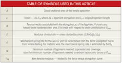
where R = tension force vector associated with elongation (applied at 54.74°, the neutral angle), N = minimum number of ligaments needed to cover the hose tube, P = hydrostatic pressure of the fluid, and DN = nipple diameter when equilibrium exists between the hydrostatic forces and the reinforcement (with reinforcement strands aligned at the neutral angle).
Reinforcement ligaments support the fluid’s hydrostatic force by tension. The ligaments align themselves so that they’re equal to, and opposite in direction to, the hydrostatic force. Ultimately, the reinforcement moves to the neutral angle. Tensile strength of the ligaments and the number of them weigh heavily in the strength of hydraulic hose.
Hose reinforcement consists of either braided or spiraled ligaments of wire or yarn wound symmetrically about the hose tube. Specifically, total tension is distributed among the total number of ligaments in the construction. Therefore, the tensile force per ligament is:
R = (P × 1.36 × DN2)/N,
which becomes the required quantity for equal load sharing.
Reinforcement is elastic
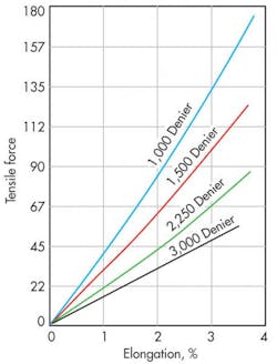
Visualize hose reinforcement as a collection of parallel springs that align themselves against the hydrostatic forces. Each hose reinforcement strand of wire or yarn is a spring that exhibits a tensile-versus-elongation result (Figure 1). This type of curve is common for both wire and yarn, and its slope, R/ε, is the spring rate, K, or yarn tensile modulus, YTM, respectively. The 1,500-Denier yarn in Figure 1 has a breaking strength, Rmax, of 87 lb and elongation of about 3.7%. So for 1,500-Denier yarn reinforcement, yarn tensile modulus is:
YTM = 87 lb/0.037 = 2,351 lb.
Therefore, for a 10-in.-long strand of yarn, YTM is 235 lb/in. Just as with a spring, YTM and K change with increasing or decreasing length.
The curves shown in Figure 1 represent four para-aramid yarns. However, metallic wire tensile tests conducted by manufacturers generate similar data. In fact, metallic-wire properties are more easily found because the metals are homogeneous, isotropic, and elastic (and not undergoing a chemical reaction). Tensile tests with heavily work-hardened metallic wire produce a straight-line curve similar to that in Figure 1. The slope of the line defines the force-to-elongation relationship between tension and elongation. The slope is a function of the modulus of elasticity, and spring rate is given by:
K = R/∆L.
So for wire reinforcement the spring rate is change in force divided by strain:
K = (E × A)/L0,
and for yarn:
YTM = R (L0 × ∆L).
Consequently, for wire, the tensile load carried by a single strand is estimated by:
R = (E × A)/L0 × ∆L.
The point is that the wire spring rate is sensitive to the original ligament length because of the wire’s fixed modulus of elasticity and cross-sectional area. Therefore, whether yarn or wire, the original ligament length is the only design variable that impacts load sharing.
Equal load sharing in reinforcement requires each strand to carry an equal portion of the load created by the fluid pressure. However, this only happens if each strand carries the same tension, and the ligaments must start out at the same length.
One consequence of the spring-rate concept is that the shorter the original ligament length, the stiffer the spring. This means shorter ligaments become loaded quicker, making them first to break. Ideally, all ligaments should load at the same rate; to accomplish this, all ligaments must be the same length.
Different designs for different pressures
Low and medium-pressure hose constructions generally need only a single reinforcement layer. The standard practice is to apply braided reinforcement at the neutral angle. Wire-reinforced hose assemblies inherently share load because wire is stiff, which makes it easier to ensure that the ligaments are of equal length — as long as the manufacturing process is well designed. Furthermore, single-layer yarn constructions are difficult to manufacture due to the noodlelike consistency of yarn. It knots, twists, and bunches in ways that don’t occur with metallic wire.
Reinforcement force must resort to multilayer construction if there’s not enough tube surface area to hold all of the ligaments. In addition, the tube cannot be 100% covered because as the hose assembly bends, the reinforcement must have space to move without interference. One proposed solution is to stagger the pitch angle of the reinforcement. Another strategy applies the strands in each layer at the neutral pitch angle and, as a consequence, with the same original length.
Issues with multi-layer construction
Multi-layer reinforcement with staggered pitch angle may apply the inside reinforcement layer at a pitch angle less than the neutral angle — say, 53°. Thus, the inside reinforcement layer “swells” to meet the upper layer. Meanwhile, the upper reinforcement layer’s pitch angle would then be greater than the neutral angle — say 56°. This would cause it to “shrink” around the inside layer. Figure 2 depicts the length of a reinforcement strand as it unwinds from the helix of one reinforcement layer. This representative geometry shows that the length of the ligament is related to the pitch angle, θ.
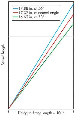
Equal load sharing requires equal reinforcement length among all ligaments, and a single-layer reinforcement construction loads to the neutral angle because the internal forces drive the ligaments to that point. So, shouldn’t the same rule apply to multiple-layer reinforced hose assemblies? To find the answer, Figure 3 graphs the lengths of unwound ligaments applied to a hose construction with pitch angles of 53°, 56°, and neutral angle of 54° 44”. The 56° ligament is about 1¼-in. longer than the 53° strand. The longer strand supports about 93% as much of the load as the shorter strand based on the calculated strain. Based on spring-rate and original ligament length, the inside layer — at a 53° pitch angle — must carry more hydrostatic pressure load than the ligaments in the outside layer.
But what if the inside strands swell as the layer moves toward the neutral angle? This phenomenon is stipulated by the force balance presented by Colin Evans in Hose Technology. It happens in a single-layer design, whereby the fittings move toward one another as the reinforcement applied at 53° moves toward the neutral angle. The question is whether the same thing will occur in a multi-layer construction.
The inner layer will carry a larger load because it has a stiffer spring rate. Furthermore, it will swell as the braid angle moves to the neutral angle (the inner ligaments will elongate some ∆L from the hydraulic forces). However, the ligaments in the outer layer will not elongate to carry load. Why not? The inner braid responds to the hydrostatic forces, so the braid angle of 53° is compelled to move toward the neutral angle. Thus, the hose segment between the fittings shortens from 10 to about 9.83 in.
So, what happens at the outer braid? Ligaments in the 56° layer are 17.88-in. long, but they can only provide reinforcement if they are strained. However, the distance between the fittings has shortened by about 0.17 in., because the reinforcement on the inside layer has moved toward the neutral angle. The resulting braid angle for the outer layer rotates to about 56.6° — and may compress! The braid angle for the upper layer rotates and, in the absence of friction, the strands may not share any load because they’re not being strained.
The load-sharing arrangement becomes less effective as the pitch angle difference increases between the upper and lower layers. The staggered braid angle geometry multilayer reinforcement solution fails as a solution because the short strands carry the majority — and possibly all — of the load.
Optimal multi-layer construction
All internal and reinforcement forces are balanced when the ligaments come to rest at the neutral angle. The internal forces cause the reinforcement ligaments to elongate in proportion to the strands’ spring rate. Equal load sharing is achieved when all ligament lengths are the same because the strain is uniform. Figure 3, again, shows the relationship between the pitch or braid angle and the ligament helix length based on a 10-in. fitting-to-fitting length. When all ligaments are applied at the neutral angle — whether there are one or 10 reinforcement layers — each will have a helix length of 17.32 in. for a 10-in. base length between fittings. The ligament length stays the same regardless of its location within a multi-layer construction, as long as it’s applied at the same pitch angle.
Because ligament length governs load sharing, it’s critical for all ligaments to be applied at the same braid angle to ensure they’re all the same length. The challenge is to make the same ligament length throughout the construction. The control strategy behind the manufacturing process is the key to optimizing hose construction.
Summarizing important points
In conclusion, the ligaments resist the hydrostatic forces by tension. The ligaments align themselves against those forces by seeking the neutral angle. All reinforcement ligaments are springs and have a spring rate expressed by its tension versus elongation ratio. The spring rate leads to the critical design and manufacturing factor — the overall ligament length as determined by the measurement from one fitting to the other. Equal load sharing requires that all of the reinforcement ligaments be applied symmetrically to ensure all are as close to the same length as manufacturing tolerances allow.
Peter Stroempl is principal engineer at Fluid Routing Solutions Inc., Lexington, Tenn. He can be reached at pstroempl@msn.com.
