Simple solutions for more-effective hydraulic filtration
Fluid cleanliness, sampling, and analysis in hydraulic machinery have long been recognized as the cornerstones for reliability centered maintenance. For this reason, most manufacturers of hydraulic components and designers of hydraulic systems recognize the value of specifying fluid cleanliness levels in their warranty. Few however, make the necessary provisions for implementing these maintenance procedures, leaving it up to the end user and aftermarket service providers.
Conventional setups
The traditional filler-breather on many hydraulic systems has a 2.88- in. bolt circle, and a basket strainer is the only filling point on the reservoir. In addition to the fillerbreather, the reservoir usually contains a drain valve and one or more unused ports for accessories, such as an immersion heater.
A reliable hydraulic system should start with a high quality and serviceable air breather. Volume changes in the hydraulic reservoir, combined with temperature fluctuations, means that the inside air space must be vented to atmosphere. Without a clean and efficient air breather, pressure rise or vacuum can occur inside the reservoir. Both are leading causes of premature failure of critical seals in the reservoir and in hydraulic pumps, cylinders, and valves.
Kidney loops
The best health care for extending the life of hydraulic systems is keeping fluid clean. Arguably, off-line (kidney loop) filtration is the earliest and most cost effective place to intervene in the ever-expanding wear cycle caused by fluid contamination.
Most discussions on off-line filtration focus on the filtration unit — not on the hydraulic systems they service. A more meaningful discussion must start at the reservoir and end with an off-line filtration system that best meets the requirements of the job.
Filtration and filter media technologies have improved immensely since in-line filters were first used decades ago. It was well understood that a machine will run longer with dirty oil than it will with no oil. Therefore, filter heads were designed with a bypass mechanism to maintain an uninterrupted flow of fluid, even when the filter element was plugged with contamination. Most filter heads today remain fundamentally unchanged.
The logic of off-line filtration recognizes that a filter in bypass is no longer part of the solution — it is part of the problem. This is because unfiltered oil continually circulates throughout the hydraulic system, including the reservoir.
A true off-line filtration system operates independent of the filtration package designed for the hydraulic system. It can be turned on or off on demand. It can also be effective with the hydraulic system running or not running. When turned on, an off-line filtration unit must ensure that any oil removed from the reservoir is filtered and returned to the reservoir at precisely the same rate.
Retrofitting the reservoir
An off-line filtration unit can be a permanent installation on the reservoir, or it can be a portable unit — typically called a filter cart — that is moved from one reservoir to another for servicing multiple machines. Whatever the choice, three prerequisites should be met before adding an off-line filtration loop to any hydraulic reservoir:
• a high quality air breather that is kept in place at all times to protect the air space in the reservoir,
• an oil outlet at the bottom of the reservoir for a suction hose to the filtration loop, and
• an oil inlet on top of the reservoir for a return hose from the filtration loop.
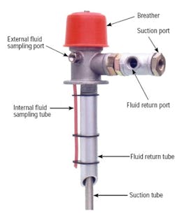
The first step in adding off-line filtration to a reservoir is to evaluate the reservoir attachments. An off-line filtration kit, Figure 1, delivers all three prerequisites in one installation, replacing the original filler-breather used on the reservoir.
The next challenge is to minimize the number of connections and length of hoses. Another challenge is to position a filter cart close to the reservoir for maximum effectiveness while also keeping it a safe distance from potentially dangerous machine elements.
On-the-go filtration
There will always be a debate over the type and number of filters used on a filter cart. The most common filter carts use two 5-in. diameter spin-on filters. The first is called the pre-filter, and the second is called the final filter. Each filter threads onto a head assembly, which contains a condition indicator and a built-in bypass valve, usually set for 25 psi. When the bypass valve begins to open in the pre-filter, unfiltered fluid passes through to the final filter. At this point, the filter cart is effectively a single filter unit.
The reservoirs that keep a facility up and running are rarely found in a maintenance shop. They are usually found on a crowded operating floor, on an overhead catwalk, at the end of ship loading boom, or 200 ft straight up in a wind turbine. Wherever the reservoir is located, the filter cart has to be pushed, pulled, dragged or otherwise transported to the reservoir.
Changing out an oil filter is a messy procedure and best done in a maintenance shop. In the maintenance shop, the issue is much more than the time and cost of changing out one filter or both filters. Change only one, and there is the risk of cross blending oil grade specifications when the filter cart is used on other applications. And then there is always the incidental costs, the disposal of oil filters and the waste of a gallon or more of hydraulic oil.
Off-line filtration
The wide variety of hydraulic grades, viscosities, and operating conditions makes selection of the right pump an important decision. If the heart of an off-line filtration system is the pump, the heart of a pump is its rotating group. The pump’s rotating group is turned by a motor to create a partial vacuum on the suction side of the pump. Vacuum draws the oil out of the reservoir through the suction hose to the pump inlet and fills the cavities of the rotating group. The rotating group carries the oil over to the pressure side of the pump and forces it through the filters, through a return hose, and back into the reservoir. The performance and efficiency of the pump is determined by the amount of oil that completely fills each cavity in the rotating group as it turns.
This establishes four external factors that will influence the performance and efficiency of the off-line filtration unit:
• inner diameter of the suction hose,
• length of suction hose and number of connections in it,
• type and configuration of the pump’s rotating group, and
• the speed of the pump’s rotating group.
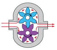
Gear pumps, Figure 2, are usually specified for off-line filtration loops. They work well with most hydraulic fluids, but their design limits their use with higher viscosity oils, especially in cold weather conditions. The small cavities created by the their spur gears, the knife edge gear tooth form, the close tolerances required for higher pressure, and the fixed outer gear housing all combine to severely limit its efficiency in an off-line application.
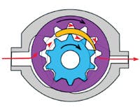
The rotating group of a gearotor pump, sometimes called a crescent pump, Figure 3, is better suited for higher viscosity fluids, especially when used under cold operating conditions. In these pumps, an internal gearotor drives an external gearotor. Inherent to the design are larger and fewer cavities with rounded corners that open and close more smoothly. This rolling action of the two gearotors delivers ripple-free flow and reduces shearing of the oil in the pump, which means less noise, less aeration, and less cavitation.
The ripple-free flow also puts less stress on the oil filter and increases dirt holding capacity of the filter media. Turning the rotating group at a lower speed improves the pump’s performance even further, particularly in cold conditions with higher viscosity fluids.
The most important feature of a filter cart is to have an adjustable relief valve built into the pump housing. This eliminates the need for a bypass valve in the filter head and ensures that only polished oil can pass through to the reservoir. When the relief valve is set at 60 to 80 psi, it significantly increases the dirt holding capacity for an oil filter that would otherwise bypass at 25 psi.
Filtration increases productivity
One feature on an off-line filtration system that pays huge dividends is a selector valve and a secondary output flow path. When a reservoir must drained, its fluid must be transferred to an oil drum for removal and subsequent recycling or other processing. A selector valve that offers a secondary, unfiltered flow path can be used to transfer this dirty oil without fouling the main oil filter. A secondary outlet can also be fitted with a backup or duplex filter so the off-line filtration can continue without having to return to the maintenance shop and service the filter cart.
For more information, contact JLM Systems Ltd. at (604) 521- 3248 or visit www.oilmiser.com.
|
A checklist for off-line filtration • Make it easy to do a better job. Pre-install hose connection points and oil sampling valves on all hydraulic reservoirs. |


