Hydraulic-Electric Analogies: Fluid and Electronic Filters
Undesirable elements found in hydraulic and electronic circuits differ in physics as well as philosophy. In principle, hydraulic filters consist of porous media that trap particles greater than a specified size to remove contaminants from the fluid, all of which are undesirable. Traditional electronic filters consist of a combination of resistors, capacitors, and inductors to take advantage of circuit resonance to perform band-blocking or bandpassing filter functions to eliminate or reduce unwanted frequencies.
Neither filter, in its respective medium, is perfect. All fluid contaminants are bad, and in an ideal world they would be zero. Moreover, all undesirable frequencies, it is hoped, are reduced to zero. Neither goal is possible, strictly speaking, nor are they necessary. It is only necessary to reduce their respective effects to acceptable levels for the application at hand.
Electronic filters are somewhat more flexible than hydraulic filters. That’s because they can be designed and implemented to not only reject certain frequencies, but also reject bands of frequencies, or accept certain frequencies or bands of frequencies while rejecting others.
Electronic filters can be active, meaning they incorporate active electronic functions (such as operational amplifiers along with resistors and capacitors), or they can be passive, meaning amplification functions are not used. These are analog devices.
When using computers to control machinery, digital filtration technology can be implemented, providing performance simply not possible in analog circuits. In any event, filter theory for both hydraulic and electronic circuits have been developed to a high level and go beyond the scope of this basic survey of analogies.
Particle Counters: A Hydraulic Filter-Testing Tool
Hydraulic particle counters do just as the name implies, and are vital to the evaluation and testing of hydraulic filters. At least three different technologies exist to count and size particulate contaminants in the hydraulic fluid, but in the interest of brevity, only one will be reviewed in this article.
Here’s an oversimplified explanation of how a particle counter works: A sample of fluid containing contaminant particles is passed through a tiny chamber with concentrated bright light impinging on it. The presence of the particle is detected optically. But more than that, by measuring the size of the particle’s shadow, the counter can determine its projected cross-sectional area. Thus, particles are able to be counted and classified according to size. Electronic (computer) processing of the particle measurements produces a summary of the fluid sample that delivers a report on the numbers of particles in each of several size ranges.
Particle counting is used to evaluate filter effectiveness by comparing the upstream particle sizes and quantities to those measured downstream of the filter. Due to the way the counter’s analyzer measures the shadow, a 3-µm particle may be circular, cubic, or oblong. Each one has the same shadow area, but longest dimensions vary from one to another.
Because the filter does not filter based upon shadow, but rather if it can be caught up in one of its apertures, an oblong particle may pass through on one pass. However, it will eventually try to pass sideways and be trapped. Thus, filters are evaluated using a multi-pass procedure. The total amount of contamination in the fluid continues to decrease in an exponential fashion with continued recirculation of the fluid. Most failures of hydraulic equipment can be traced to poor fluid-cleanliness practices.
Contaminant Sources and Corrective Actions
Several decades of applied research at Oklahoma State University’s Fluid Power Research Center, supported and sponsored by OEM firms, revealed the common sources of contamination in a hydraulic system:
1. New hydraulic fluid is not clean enough for use in high-pressure hydraulic systems. Fluid should be filtered before being introduced into the hydraulic reservoir.
2. New components have manufacturing debris that is harmful. Cleanliness standards have made manufacturers aware of the problems, leading to improved pre-shipment component cleanups.
3. Contaminants are ingressed through breather caps in fluid reservoirs. Breather-cap filters have to be of the same quality and contaminant trapping as the main system filters.
4. Contaminants are ingressed via cylinder rod retractions as a result of normal operations. This knowledge has led to improved rod seals, and it points out the need for proper filtration on an ongoing basis.
5. Poor user maintenance practices have been a major source of hydraulic fluid contamination. Education has led to user enlightenment.
Attitudes toward fluid cleanliness have evolved since World War II. I have seen user attitudes go from “we remove the filters because they just plug up” to “it’s essential that we get the components clean, the fluid clean, and then keep it clean.” The reward is more reliable machinery and less downtime.
Filter technology has advanced considerably in recent decades due to industrial and academic research-and-development efforts. The status of the filter element is best indicated by the differential pressure drop across the filter. As it continues to do its removal work, the myriad tiny flow paths become blocked by particles accumulating in them.
Some filters are equipped with integral low-pressure relief valves that allow fluid to bypass should the filter become seriously restricted. The rationale is that it is a safer situation to enable contaminated fluid to circulate through the system than to allow all flow to be blocked. But, obviously, the filter element should have been changed before the occurrence of such an extreme condition.
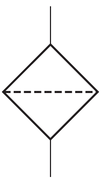
The standard ISO filter schematic symbol is shown Fig. 1. They are normally drawn with fluid entering the upper port and leaving through the lower. However, that is merely common practice, not standardized practice.
Electronic Filters
Analog tuning of AM (amplitude modulation) and FM (frequency modulation) radios is a filtering process. Radio stations transmit signals in the AM band between 540 and 1600 kHz, with stations transmitting on even multiples of 10 kHz; for example, 540, 550, 560, . . . 1580, 1590, and 1600 kHz. These are called carrier frequencies. An antenna is nominally sized to capture all transmitted frequencies.
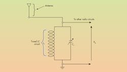
Tuning is received using a capacitor-inductor circuit with variable capacitance that shorts out all frequencies except one. For example, a popular local AM station in Milwaukee is WTMJ, which transmits on 620 kHz. If you want to listen to that station, the capacitor is tuned until 620 kHz is isolated and amplified, while all other frequencies are effectively shorted to ground. Successful tuning is signaled by watching the tuning dial as well as listening for the intended audio.
FM stations transmit on carrier frequencies between 88 and 108 MHz. Stations are selected in a similar manner, but at much higher frequencies. Today’s radio receivers use digital filter tuning, which is more amenable to such user-friendly amenities as pushbutton tuning, station seeking, and aiding and improving station separation—another term for enhanced station selection. The key is a variable filter.
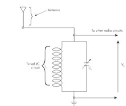
Figure 2 shows a schematic diagram of the resonant inductance and capacitance in parallel that will select only one of several transmitted frequencies (stations). It also shows the receiving antenna that captures the signals from all nearby stations; however, the resonant circuit will sort all signal frequencies to ground.
Other electronic filters are utilized to control background noise, which can occur in any circuit. Noise in this context is not necessarily heard, but that could be the case. Instead, it is any unwanted signal, such as hum in your expensive entertainment center or the interference that comes through an AM radio when you drive under a high-voltage power-transmission line.
When this occurs, the interference comes in through all possible means, including the antenna, but it can also get induced directly into the other stages within the radio receiver. For instance, a TV transmitting antenna can be pumping out as much as 100,000 W of radio-frequency (RF) power.
A TV antenna is like the primary winding of a transformer, and every antenna and every piece of conductor within 50 miles is like a transformer secondary winding with one turn. The result is that every conductor in the car and radio will get some TV RF-induced into it and distort the station to which the radio is tuned. When an AM radio is within a mile or two of the TV transmitter, only the most selective tuning circuit can keep the interference outside the radio receiver.
Noise in Electrohydraulics
Such induced voltages can be dangerous in electrohydraulic machinery because the induced signals can provoke electrohydraulic pumps to change settings, causing electrohydraulic valves to shift at unexpected times and ways. It is essential that control electronic devices be evaluated as to their susceptibility to these stray electronic noises.
Standardized and certified test methods can be conducted for electromagnetic compatibility (EMC). Compatibility means that the control circuits are able to reject the stray signals. Stray noise signals may enter the circuit by several means, such as through the external power supply connections. Others are induced directly into the circuit-board conductors and components.
The EMC test procedure involves placing the tested circuit inside an enclosure shielded from external RF radiation and then generating controlled radiation within the enclosure while measuring the tested circuit’s reaction. The aim is to make the circuit impervious to the effects of external radiation. Tests are conducted on an entire mobile vehicle when noise signal infiltration can impact safe operation of the vehicle.
Electronic filter design is a technical specialty in itself, and has reached a high state of the art. Advanced types include notch filters, which can reject a specific frequency. They are sometimes used in poorly behaved feedback-control systems. Another is the Butterworth filter, which can reject all frequencies above a specifiable maximum with any desired degree of sharpness in the cutoff. Kalman filters are digital and implemented in software, but they need computer control systems to make mathematical calculations. Moving average is another form of digital filter that can help remove abrupt changes in the output of transducers and other signals.


