Five Must-Knows for Successful Hydraulic Filter Sizing
Every industry, machine, and component within a hydraulic system brings its own set of requirements, each affecting the other to eventually influence selection of a seemingly simple filter element. Before setting yourself up for unintentionally higher operating costs, you should not only select a filter based on pressure, flow, and cleanliness level required, but have a good feel for the big picture. Described here are five crucial pieces of information to know before sizing and selecting a filter.
1. Know the Application
Let’s start broad. First and foremost, understand the performance requirements of the filter. When it comes to accurately sizing a filter, performance requirements are often expressed in terms of Beta ratio, which is simply the ratio of particles entering the filter versus those exiting. Beta ratios can also be expressed as an efficiency percentage.
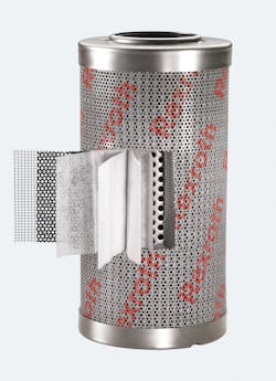
Today’s hydraulic filters are designed with media to trap and hold more contamination particles than ever for long life and low pressure drop.
For example, an application requiring a high-performance element will often have a Beta ratio exceeding 1,000, where 1,000 particles enter the filter but only one particle makes it out. Element performance in this scenario would be expressed in terms of a 99.9% efficiency. A reputable filter manufacturer will have documentation defining their element performance by the element’s pore-size rating. But having a strong understanding of the application’s performance requirements empowers you to enter the filter sizing and search stage equipped for success.
2. Know the Hydraulics
Once you’ve established the performance requirement of the application, it’s time to evaluate the hydraulic system. The hydraulic components installed in the circuit directly affect the type of hydraulic filter needed to function according to industry standards. This criterion drives an ISO-cleanliness code requirement that helps dictate the proper filter element type. As an example, a proportional valve in the circuit might require a 20/18/15 ISO-cleanliness code. To meet the standard set by the ISO code, this circuit requires a filter with either 3 or 6 µm absolute filtration.
Sizing filters involves selecting the best combination of dirt-holding capacity, pressure drop, and economy to match the application at hand.
However, the circuit may contain just a gear pump and directional-control valve in the circuit. Because a gear pump and directional-control valve are relatively tolerant of dirt, a coarser, lower performance filtration option—such as paper or wire mesh nominal filtration—could be a suitable option. Knowing what hydraulic components will accompany the filter and understanding how they impact filter performance requirements can save unnecessary costs in the long run.
3. Know the Viscosity
One variable often underestimated when selecting a filter is fluid viscosity. In reality, viscosity has a significant impact on filter sizing. Fluid viscosity is sometimes overlooked in the early stages of sizing hydraulic filters. As a result, filters larger than otherwise necessary may be specified, resulting in unnecessarily high operating costs.
Not understanding the importance of fluid viscosity can lead to under sizing the filter, high pressure drop, and premature tripping of clogging indicators. Conversely, oversizing the filter can contribute to higher costs, a larger footprint, and higher replacement costs. Users should understand the hydraulic system enough to estimate the normal temperature range so that the most accurate minimum temperature is selected for sizing purposes. Properly selecting the correct operating temperature range will ensure that the filter doesn’t prematurely go into bypass mode and will avoid specifying a larger filter than needed.
4. Know the Clogging Indicator
Assuming a system’s filter has a clogging indicator (analog or digital), users should create an appropriate target for a low pressure drop when sizing filters. Generally, clogging indicators a differential pressure ranging from 1 to 8 bar. As a general rule, the ratio of the clogging indicator setting to the clean pressure drop should be at least 3:1.
For example, assume a filter has a 5-bar optical clogging indicator. Based on our ratio, the highest acceptable clean pressure drop target would be approximately 1.7 bar. By not understanding the impact of this principle, users are at risk of sizing their filters incorrectly, whether too large or too small. Although oversizing filters is a commonly-used practice to ensure the highest amount of protection, the consequence is that it adds cost to the circuit.
5. Know the Flow Rate
Careful consideration of the flow rate is extremely important when sizing filters. Rexroth recommends that the maximum flow rate be considered in this measurement. Also note that intermittent flows can far exceed the pump’s maximum flow. An example of this scenario is an accumulator circuit where the accumulator stores of volume of pressurized fluid and releases it to the system to supplement pump flow. The flow rate through a pressure filter immediately downstream of the accumulator should take this additional flow into account. Underestimating the flow rate through the filter increases pressure drop through the filter element, which reduces efficiency of the circuit and increases operating and maintenance costs.
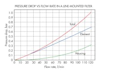
This chart illustrates performance of hydraulic filter designed to offer low pressure drop even at relatively high flow rates—a more cost-effective solution than specifying a larger filter.
Correctly sizing a hydraulic filter not only saves money, but also increases the life of the hydraulic system. In addition to the five factors explained here, even more variables should be considered before making an educated choice. To make the task less daunting, manufacturers have developed free online tools to aid selecting and sizing filters. Bosch Rexroth’s tool is called Filter Select, and is accompanied by a mobile app called Fit4Filter. Simply open the application, enter the necessary information as guided by the tool, and recommendations will be made.
Filter sizing is crucial, but the process does not have to be overwhelming. Determine these must-knows and you are well on the way to filter success.
Bill Novak is product manager, Bosch Rexroth Corp. For more information Bosch Rexroth’s online tools, click here.
About the Author
Bill Novak
Product Manager

Leaders relevant to this article:


