Hydraulic fluids perform four basic functions. Their primary function is to create force and motion as flow converts to pressure near the point of use. Second, by occupying the space between metal surfaces, the fluid forms a seal, which provides a pressure barrier and helps exclude contaminants. A third and often misunderstood function is lubrication of metal surfaces. The fourth and final function is to cool system components.
If any one of these functions becomes impaired, the hydraulic system will not perform as designed, and perhaps lead to sudden and catastrophic failure. The resulting downtime can easily cost a large manufacturing plant thousands of dollars an hour. Hydraulic-fluid maintenance, which involves implementation of a continuous program to minimize and remove contaminants, can help prevent or reduce those unplanned downtimes.
Aside from human interference, the most common source of system impairment is fluid contamination. Contamination can exist as solid particles, water, air, or reactive chemicals, all of which impair fluid functions in one way or another.
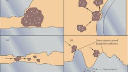
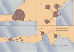
As the figure below shows, three-body mechanical interactions can result in interference (a). Two-body wear is a common occurrence in hydraulic components (b). Hard particles can create three-body wear to generate more particles (c). In addition, particle effects can trigger surface wear (d).
Sources of contaminants
Contaminants enter a hydraulic system in various ways, such as:
• Built-in during manufacturing and assembly processes
• Internal generation during normal operation
• Ingested from outside the system during normal operation
If not properly flushed out, contaminants from manufacturing and assembly will be left in the system. These contaminants include dust, welding slag, rubber particles from hoses and seals, sand from castings, and metal debris from machined components. Also, fluid that’s initially added to the system probably comes with a certain amount of contamination, such as various types of dust particles and water.
During system operation, dust also enters through breather caps, imperfect seals, and any other openings. Furthermore, system operation generates internal contamination. This occurs as component wear debris and chemical byproducts from fluid and additive breakdown due to heat or chemical reactions. Such materials then react with component surfaces to create even more contaminants.
Contaminant interference
In broad terms, contaminant interference manifests itself as either mechanical or chemical interaction with components, fluid, or fluid additives. Mechanical interactions range from blockage of passages by hard or soft solid particles, to wear between particles and component surfaces (see the figure). Chemical reactions include formation of rust or other oxidation, conversion of the fluid into unwanted compounds, depletion of additives (sometimes involving harmful byproducts), and production of biochemicals by microbes in the fluid.
Any of these interactions will be harmful. Without preventive measures and fluid conditioning, their negative effects can escalate to the point of component failure. One of the most common failure modes is excessive wear due to loss of lubrication.
Filter media
The filter media is the part of the element that actually contacts a contaminant and captures it for subsequent removal. The nature of the particular filter media and the contaminant-loading process designed into the element explains why some elements last longer in service than others.
During manufacture, media usually starts out in sheet form, and then is pleated to expose more surface area to the fluid flow. This reduces pressure differential across the element while increasing dirt-holding capacity. In some designs, the filter media may have multiple layers and mesh backing to achieve certain performance criteria. After being pleated and cut to the proper length, the two ends are fastened together using a special clip, adhesive, or other seaming arrangement to form a cylinder. The most common media include wire mesh, cellulose, and fiberglass composites, or other synthetic materials.
Filter media is generally classified as either surface or depth type:
Surface media: For surface-type filter media, the fluid stream flows in a straight path through the element. Dirt is captured on the surface of the element facing the fluid flow. Surface-type elements are generally made from woven-wire cloth. Because the process used to manufacture the wire cloth can be controlled very accurately, and the wire is relatively stiff, surface-type media have a consistent pore size. This consistent pore size is the diameter of the largest hard spherical particle that will pass through the media under specified test conditions. However, during use, the build-up of dirt on the element surface will reduce the pore size and allow the media to capture particles smaller than the original pore-size rating. Conversely, particles (such as fiber strands) that have smaller diameters but greater length than the pore size may pass downstream through surface media.
Depth media: For depth-type filter media, fluid is forced to take convoluted, indirect paths through the element. Because of its construction, depth-type media have many pores of various sizes formed by the media fibers. This maze of multi-sized openings throughout the material traps contaminant particles. Depending on the distribution of pore sizes, the media can have a very high capture rate for very small particle sizes.
The two basic media used for depth-type filter elements are cellulose (or paper) and fiberglass. The pores in cellulose media tend to have a broad range of sizes and are very irregular in shape due to the irregular size and shape of the fibers. In contrast, fiberglass media consist of synthetic fibers very uniform in size and shape. These fibers, generally thinner than cellulose fibers, have a consistently circular cross-section. The differences between these typical fibers account for the performance advantage of fiberglass media.
Thinner fibers can provide more pores in a given area. Furthermore, thinner fibers can be arranged closer together to produce smaller pores for finer filtration, resulting in improved dirt-holding capacity and filtration efficiency.
Filter types and locations
The type of filter—suction, return, pressure, or off-line—and its physical location in the circuit are almost inseparable by definition.
Suction filters serve to protect the pump from fluid contamination. They are located upstream from the pump’s inlet port. Some may be simple inlet strainers, submersed in fluid in the tank. Others may be mounted externally. In either case, suction filters have relatively coarse elements, due to cavitation limitations of pumps. (Some pump manufacturers do not recommend the use of a suction filter; always consult the pump manufacturer for inlet restrictions.) For this reason, suction filters don’t serve as a system’s primary protection against contamination. In fact, the use of suction strainers and filters has signifcantly decreased in modern hydraulic equipment.
Return filters may be the best choice if the pump is particularly sensitive to contamination. In most systems, the return filter is the last component that fluid passes through before entering the reservoir. Therefore, it captures wear debris from all of the system’s working components and any particles that enter through worn cylinder rod seals before such contaminant can enter the reservoir and be pumped back into the system. Because this filter is located immediately upstream from the reservoir, its pressure rating and cost can be relatively low.
Note that retracting some cylinders with large diameter rods may result in flow multiplication. This high return-line flow rate may open the filter bypass valve, allowing unfiltered fluid to pass downstream. This probably is an undesirable condition and should be considered when specifying the filter.
Pressure filters, located downstream from the system pump, handle the system pressure. They are sized for the specific flow rate at their location along the pressure line. Pressure filters are especially suited for protecting sensitive components, such as servovalves, directly downstream from the filter. Because pressure filters are located just downstream from the pump, they also help protect the entire system from any pump-generated contamination.
Duplex filters, a common special configuration, may include both pressure and return filters. Duplex filters provide continuous filtration. They have two or more filter chambers with internal passageways and valves to allow for uninterrupted operation. When one filter element needs servicing, the duplex valve is shifted, diverting flow to the opposite filter chamber. Then the dirty element can be changed, while flow continues to pass through the cleaner element. The duplex valve typically is an open crossover type, which prevents any flow blockage.
Off-line filtration operates independent of a machine’s main hydraulic system. This increasingly popular filtration arrangement (also referred to as recirculating, kidney loop, or auxiliary filtration) is attractive as a retrofit project for problem systems. An off-line filtration circuit includes its own pump and electric motor, a filter, and the appropriate connecting hardware. These components are installed off-line as a small subsystem separate from the working lines, or they may be included in a fluid-cooling loop. Fluid is pumped continuously out of the reservoir, through the off-line filter, and back to the reservoir. A rule of thumb: The off-line pump should be sized to flow a minimum of 10% of the main reservoir volume.
With its polishing effect, off-line filtration is able to maintain the system’s fluid at a constant contamination level. As with a return line filter, the off-line loop is best suited to maintain overall system cleanliness; it doesn’t provide protection for specific components. An added advantage of an off-line filtration loop is that it’s relatively easy to retrofit on an existing system with inadequate filtration. Also, the off-line filter can be serviced without shutting down the main system.
About the Author

Leaders relevant to this article:

