Contamination control involves preventing contaminants from entering a hydraulic system and placing filters in strategic locations throughout the system to trap any contaminants that do find their way into the fluid. But for critical equipment, a successful contamination control program also must include regular assessment of the hydraulic fluid's cleanliness. Often, this must be done every two to six months or after every 500 or 1,000 hours of operation, depending on the equipment's duty cycle, operating environment, and how critical it is to overall operation.
Experts also recommend that fluid be tested immediately after any maintenance event that exposes the hydraulic system to the external environment. This could be when a hose or other component is replaced or fluid is added to the reservoir. Fluid replenishment can be particularly troublesome because new fluid is notorious for being dirty - often from improper storage and handling practices.
Test labs or do-it-yourself?
Before the advent of portable contamination detection instruments, fluid testing was conducted for only the most critical equipment and sent to a laboratory for analysis. This is still the most practical route for companies that do not require fluid testing often enough to justify purchasing their own diagnostic equipment and training their personnel. And even if a company has its own equipment, test labs still prove valuable for running multiple tests, interpreting results, troubleshooting, and recommending appropriate action.
Test labs should also be consulted for periodic chemical analysis of hydraulic fluid. Even if contamination has been brought to within acceptable limits, certain contaminants can alter a fluid's chemical composition (primarily the additives) and render it ineffective. For example, additive depletion, over time, can reduce a fluid's lubricity, oxidation resistance, or anti-foaming characteristics.
Excessive water and overheating are two conditions that can upset a fluid's chemical balance relatively quickly. Therefore, if excessive water is found in a fluid or a system overheats, experts recommend not only finding and correcting the source of the problem, but conducting chemical analysis of the fluid as well. Even if these problems do not occur, hydraulic fluid suppliers generally recommend having fluid analyzed chemically at regular intervals — such as annually — to identify potential problems and prevent them from occurring.
Portable particle counters and other diagnostic equipment have made it easy and convenient to monitor fluid cleanliness of even non-critical equipment. In fact, many companies that have invested in their own particle counters and other instruments monitor cleanliness of more equipment more often.
The higher reliability that results from this more-intense preventive maintenance adds to the return on their investment. Furthermore, advanced techniques are being developed to make fluid-monitoring instruments even more sophisticated. Equipment currently is under development to continuously monitor the condition of hydraulic fluid while equipment is running.
Assessment starts with a sample
Regardless of the details of any contamination-monitoring program, its usefulness will depend on fluid sampling. Fluid samples must accurately represent the condition of the fluid within the hydraulic system. This means that the sampling technique and devices, as well as the container, must not contaminate the fluid sample.
The point from which samples are extracted should be determined by the information desired from the sample. For example, sampling fluid from a system's pump discharge line will likely produce different results from a sample taken from a return line. Fluid from the pump discharge line is more likely to contain pump wear debris than fluid from a return line because filters would have captured pump wear debris before it would reach a return line.
Experts advise, however, that samples taken from the reservoir usually are the most unreliable. First, because a reservoir acts as a storage device, its contents have accumulated over a relatively long interval, whereas fluid from a hydraulic line is more representative of conditions at the time the sample is taken. Second, most reservoirs are designed to minimize turbulent flow so contaminants can settle to the bottom and air can rise to the top. This makes it difficult to obtain a sample with a representative concentration of water and other contaminants.
Fluid analysis techniques
Once fluid samples have been obtained, any of several methods can be used to analyze the size, concentration, and nature of the contaminants. The most common analysis techniques for hydraulic systems are:
• particle distribution
• gravimetric
• ferrographic wear debris
• proton induced X-ray, and
• water content.
Each of these tests produces different results according to the type of information desired. Therefore, they should not be viewed as competing technologies. Rather, the more tests that are conducted on a sample, the more knowledge that can be gained. But no matter which technique is employed, obtaining a pure and representative sample is essential to achieving accurate results.
Particle distribution summarizes the number of contaminant particles classified by size for a sample. Automatic particle counters have gained wide acceptance for this previously time-consuming, laborious task that produced inconsistent results. The widespread use of particle counters is a testament to their ease of use and consistent reliability. They are often used by technicians at manufacturing and maintenance facilities.
Gravimetric analysis summarizes the total mass of solid particles above a given size for a specific volume of fluid. Results are reported as mass density, usually mg/l. Unlike particle counting, gravimetric analysis quantifies only solid particles, not water.
However, gravimetric analysis gives no indication of size distribution. So a sample may contain 25 mg/l of solid particles greater than, say, 5 µm. But this gives no indication as to what percentage of particles are greater than 10 µm and how many are greater than 15 or even 25 µm. As with particle counters, gravimetric analysis instruments often are used by technicians to monitor contaminants in hydraulic systems.
Ferrographic wear debris analysis quantifies wear debris (primarily metals) in a fluid sample. Because the most highly stressed wearing parts of of machine components are made of steel, wear debris usually are influenced by magnetic fields. Ferrographic analysis can be used to evaluate a system's wear mechanisms, assess the severity of wear, and identify the predominant materials being worn away.
Proton-induced X-ray emission (PIXE) summarizes the elemental composition of solid contaminants and wear debris in a fluid. The procedure involves exposing the fluid sample to a proton beam. A computer then interprets results of the test by producing data on the entire spectrum of elements in the target, not just a single element.
Neither particle counting nor gravimetric techniques can differentiate between foreign contaminants and wear debris, which makes PIXE useful for gaining insight into the nature of particles found in a fluid.
Water-content analysis determines how much water is present in a base fluid. Next to particulate matter, water, by far, is the most damaging contaminant in a hydraulic system - or any oil-lubricated system for that matter. Higher concentrations of water in hydraulic oil accelerate wear, fluid degradation, corrosion, and reduction in service life. Therefore, once the amount of water present in a hydraulic fluid has been found, the challenge becomes determining how much can be tolerated.
The test itself uses a solution that conducts electrical current based, in part, on the amount of water contained in a sample. Measuring the current and its duration provides an indication of water content in the base fluid. The test can be accurate to within 10 ppm, but additive packages common to hydraulic fluid tend to produce less detailed results.
New technology enhances assessment
Whether your car has an "idiot light" or a real temperature gauge, its designers deemed the engine's water temperature important enough to monitor it continuously. After all, it wouldn't do much good to have your engine's water temperature checked only when you stop for gas. It's much more likely that a problem would occur while you were on the road rather than when you were at the gas station.
Monitoring contamination of hydraulic fluid would at first seem to be much less critical than engine water temperature. After all, fluid usually becomes contaminated gradually, so monitoring its condition frequently enough can identify problems before they cause any real harm. Engine temperature, however, can increase quickly once a problem occurs. If a hose ruptures, the water pump gives out, or the radiator leaks, the engine can quickly overheat.
Contamination, under certain conditions, can also act quickly to cause catastrophic failure in a hydraulic system. For example, if a pump ingests enough air to cause serious cavitation, it can become inoperative within days. Or if a large quantity of water flows through a system, hydraulic fluid can lose its lubricity, which will result in rapid wear of components. If either of these events occurred a few weeks before a scheduled fluid analysis, the machine could undergo costly downtime.
Granted, these types of problems happen rarely. But if the equipment costs millions of dollars or works in an operation where downtime is measured in thousands of dollars per hour, it becomes practical to continuously monitor fluid cleanliness. It is for cases like these that companies are developing systems to monitor the cleanliness of hydraulic fluid continuously while a system is running.
One such prototype system routes pressurized fluid from the pump into a tube through which light is transmitted. When the fluid is clean and relatively free of air and water, a receptor detects the amount and pattern of light transmitted through the fluid.
As the fluid becomes more contaminated, the amount and diffraction of light transmitted through the tube changes. If undissolved water or air is present, the transmitted light becomes more scattered. Calibrating the receptor to these different conditions provides an instantaneous indication of the fluids condition. Therefore, a potentially catastrophic failure can be averted by taking appropriate action immediately.
Another emerging technology is a system that enables users to go beyond particle counting and actually analyze wear debris. The system consists of hardware to generate digital photomicrographs and software to aid in analyzing the digital images. Once imported to a PC, images can be compared to those in an atlas of known wear debris using wear debris analysis software. The software also aids in characterizing descriptions, managing data, and generating reports. The analysis can also be incorporated into maintenance and SPC software used for plant operation and quality assessment.Special fittings help keep samples clean
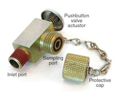
Tapping into a hydraulic system to sample fluid creates the potential to contaminate not only the fluid in the hydraulic system, but the fluid sample as well. To help prevent either from occurring, test ports designed for fluid sampling should be mounted permanently to the equipment and have protective caps to keep dirt away from the sampling port. The cap is removed only when taking a fluid sample and replaced immediately afterward.
Shown at right is a low-pressure test fitting for sampling fluid from hydraulic return lines without having to shut down equipment. Pressing on the pushbutton opens a check valve that routes fluid from the hydraulic system out through the sampling port. Models for taking samples from high-pressure lines work in a similar fashion, but use a threaded connection instead of a pushbutton to open the check valve.
The test port avoids introducing external contaminants into the fluid extracted from the hydraulic system. However, to ensure accurate samples, tubing leading to the sampling vessel and the sampling vessel itself must be absolutely clean. The tube should be discarded after a sample is drawn and replaced with a new one before each subsequent sampling.
About the Author

Leaders relevant to this article:


