Engineering Essentials: Hydraulic Motor Circuits
Download this article in .PDF format
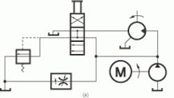
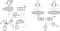
Driving a fixed-displacement fluid motor at constant pressure produces a constant torque drive, left. Used with a variable-volume pump to vary flow, the horsepower output of the motor varies with speed. If the load becomes excessive, pressure rises to actuate the pressure switch, de-energizing the solenoid valve - pump unloads, fluid motor stops.
In the right-hand drawing, a fixed-displacement pump supplying a variable-displacement motor at constant pressure produces a constant-horsepower drive. The motor produces lowest speed and highest torque when displacement is maximum. Highest speed and lowest torque are produced when the displacement is minimum.
Braking
When pump delivery is cut off, it continues rotating because of its inertia and that of the connected load. The motor then acts as a pump, and a source of fluid must be available to prevent cavitation. In (a), the manual valve allows coasting, as well as the normal driving condition of the motor. With the valve spool up, the pump output drives the fluid motor. With the spool centered, pump output and both sides of the fluid motor are connected to tank, so the motor coasts to a stop. With the valve spool down, the pump is unloaded and the motor, acting as a pump, forces fluid through the relief valve, which brakes it to a stop. Circuit (b) shows a brake valve that is a modified sequence valve. It supplies braking force as well as control of a negative work load. Under normal conditions, system pressure holds the brake valve open for free discharge from the motor. A negative load reduces pressure at the motor inlet, and the brake valve closes to throttle motor discharge and create a backpressure.
Series connection (left)
Connecting two fluid motors in series minimizes pump size and eliminates the need for a flow divider. Line sizes are also smaller than in a comparable parallel circuit, and piping is usually simpler, with only one pressure line and one return line required. Maximum torque at each motor is adjustable with the relief valves. The speed of motor A is controlled by the bleed-off flow control valve. Direction of motor B is controlled by the 4-way valve, which has an integral 2-way valve, which vents the relief valve when the motor is stopped. Total system pressure is then available at motor A.
Parallel connection (right)
Pump pressure can be lower in a parallel circuit because in a series circuit the pressure at the pump must be the sum of the pressure drops across the motors. However, where motor pressures vary widely, there is a loss of efficiency in supplying the motors requiring lower pressures. This circuit is most efficient where the load on each motor is the same. Raising the pressure on one motor renders the others less efficient and may disrupt the speed relationship. In parallel circuits, the only way to increase torque of the highest-pressure motor is to increase system pressure.
Replenishing
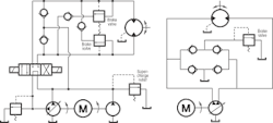
When a fluid motor and pump are connected in a closed circuit, make-up fluid to compensate for the leakage must be supplied through replenishing valves. These valves also supply fluid to the motor during braking. In the left-hand circuit, a non-reversing variable volume pump is used and control of fluid motor direction is by the 4-way valve. The fixed displacement pump provides supercharge pressure. The network of check and relief valves provides for replenishing and braking in either direction. Braking pressure in each direction can be set independently on the two brake valves. In the right-hand circuit, a reversing pump is used. Although the replenishing network is simpler, brake pressure must be the same in both directions.
About the Author

Leaders relevant to this article:


