Linearized Model of a Hydraulic Motor
Most motion-control applications are of a critical nature — they must meet accuracy, bandwidth, or some other performance demand. The most sensible and expedient way to design such systems is to use performance requirements as the design goals at the very outset of the design process. The techniques are analytical in nature, so they require mathematical descriptions of all elements of the system. Only then can synthesis and simulation methods be applied to direct the design process toward the end result without undue trial-and-error techniques. This is how motion-control and mathematical models complement and enhance one another.
The nature of the mathematical model is dictated as much by the intended use as it is by the nature of the device being modeled. Individual modelers’ beliefs and biases have been known to influence models, too. However, most designers would agree that models fall into two broad categories: steady state and dynamic. A hydraulic motor will be modeled in steady state and analyzed through some examples of how the models can be used.
Hydraulic motor models
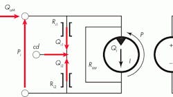
The analytical schematic of the hydraulic motor has three internal leakage paths, and one internal friction-windage resistance. However, note in Figure 1, that output is mechanical power in the form of speed and torque, whereas the input is hydraulic in the form of pressure and flow. We’ll begin by visualizing the real physical processes that the three leakage resistances represent in, say, a piston motor.
First, a direct path exists between the rotating barrel and the port plate, characterized by the laminar leakage resistance, RIpp. Second, there is a leakage from the high-pressure side, past the pistons and their bores, that ends up in the motor case. Another leakage component feeds the slipper faces through the piston centers and also leads to the motor case. Its leakage resistance is symbolized by Rı1. Lastly, the same effects exist on the low-pressure side, leading to a low-pressure leakage component to case drain. It is characterized by Rı2.
In addition, friction and windage account for a torque loss that depends on speed. It is symbolized with Rfw in Figure 1. This completes the steady-state, high-speed, linearized mathematical model of a hydraulic motor. It can be used on any motor type, provided sufficient data exists to evaluate the leakage resistance and the friction and windage resistance.
An application scenario
Imagine a hydraulic motor has been tested at a load torque of 823 lb-in. at 2,400 rpm. The inlet supply pressure was 3,000 psi while the motor outlet and case drain were essentially at 0 psig. The case-drain flow was measured at 3.39 in.3/sec and the motor inlet flow was 82.9 in.3/sec. If the motor has a displacement of 1.88 in.3/rev, determine the values for Rı1 and Rfw.
With outlet and case-drain ports at zero pressure, the full 3,000 psi is impressed across Rı1, Rpp, and the ideal displacement element of the motor. First, we need to find the ideal flow, QI, using the well-known relationship:
We can calculate the Rı1 coefficient directly from given data by assuming that the leakage flow is laminar and, therefore, directly proportional to pressure and inversely proportional to the resistance coefficient:
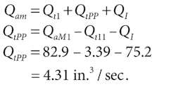
Input flow continuity requires that:
Now the port-to-port leakage resistance can be found:
To find the friction resistance, we must first calculate the ideal torque using the well-known relationship between inlet differential pressure and output torque in the ideal motor:
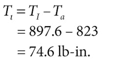
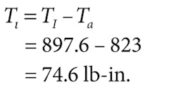
The measured torque was given as 823 lb-in. Therefore, the total friction torque loss is:
Because we assume that this is all viscous friction loss, and that the loss is directly proportional to speed, then:
Now the coefficients for the motor model have been evaluated. Formulas for calculating leakage resistance directly from motor efficiencies exist, but space prevents their inclusion here. Most technical data sheets on motors lack a specific value of case-drain leakage, which is necessary to evaluate port-to-case-drain resistance. The motor manufacturer must be consulted for that information.
Adding proportional control
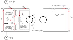
Now consider that the same motor is being used in a circuit controlled by a proportional valve. A low-pressure shaft seal in the motor allows case drain flow to return to tank through separate plumbing. Due to valve pressure drops, pressure is 2,160 psig at the motor inlet port, 915 psig at the motor outlet port, and the motor shaft spins at 1,722 rpm. Assuming that Rı1 = Rı2, we will calculate case-drain flow, motor-inlet flow, motor-outlet flow, and load torque.
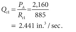
We’ll start with Figure 2, an illustration of an analytical schematic that lists all the known values. Notice that the entire supply pressure is impressed across the leakage resistance (Rı1). Therefore:
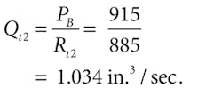
Similarly, the outlet pressure, Pb, is impressed across R2, therefore:
The motor differential pressure is impressed across the port-to-port leakage resistance:
The operating speed is given as 1,722 rpm, therefore, the ideal flow can be found:
The total inlet flow is found using the summation of flows at the A-port node:
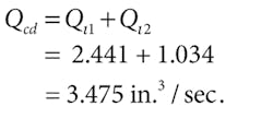
The case-drain flow is the sum of two components:
The outlet flow is comprised of three components:
The load torque can be found by first calculating the ideal torque:
The load torque is the ideal torque less the loss due to viscous friction:
Now:
Summarizing, then, case-drain flow (Qcd) is 3.475 in.3/sec; motor-inlet flow (QaMi) is 58.19 in.3/sec; motor-outlet flow (QaMo) is 54.72 in.3/sec; and load torque (ToM) is 144.45 lb-in.
Synchronizing the speed of two motors
Hydraulic-system designers often connect two motors in series in an attempt to synchronize their speeds. In principle, this is a sound idea. In actuality, however, the degree of synchronizing is imperfect because of finite internal leakage resistances. The accompanying box illustrates a practical use of a mathematical model to quantify the degree of this nonequality of the two motor speeds.
Connecting two hydraulic motors in series in an attempt to synchronize their speeds is a sound idea. In reality, though, the synchronization is imperfect because of internal leakage resistances. We’ll now examine a scenario using a mathematical model to quantify the inequality of the two motor speeds.
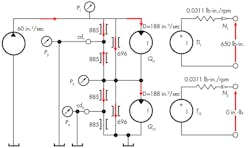
Assume two hydraulic motors — each identical to that described previously — are to be connected in series and powered by a 60-in.3/sec constant-flow source. As shown in Figure 3, the outlet port of the low-pressure motor is connected directly to tank, as are both case-drain ports. The high-pressure motor is connected to a 650-lb-in. load, but the shaft of the low-pressure motor is completely free. Both motors have a displacement of 1.88 in.3/rev; leakage resistance from each motor port to case of 885 psi/(in.3/sec); port-to-port leakage resistance of 696 psi/(in.3/sec); and torque loss from friction and windage of 0.031 lb-in./rpm.
There are four unknowns: P1, P2, N1, and N2, so four equations will be written and solved simultaneously. Note from the illustration that P4 and P3 equal 0. Two node equations represent the summation of flows (P1 and P2 nodes) and two torque summation equations (N1 and N2).
Flow summation at P1:
Flow summation at P2:
Torque summation at N1:
Torque summation at N1:
Substitution and linear algebra matrix are two common methods of solving four equations with four unknowns. However, the most practical method is by computer, and all popular spreadsheet programs have a simultaneous equation-solving capability. I solved these equations using the eQsolver capability in IDAS Engineering software. The results are:
P1 = 2,537 psig,
P2 = 186.6 psig,
N1 = 1,716 rpm, and
N2 = 1,802 rpm.
The solution to this problem demonstrates that there is nearly a 100-rpm difference between the two motor speeds. If we now solve the problem with the loads reversed (the upper motor is unloaded and the lower motor is loaded) we find that:
P1 = 2,521 psig,
P2 = 2,333 psig,
N1 = 1,815 rpm, and
N2 = 1,549 rpm.
This solution shows that there is nearly a 300-rpm change in the speed of the lower motor — a condition that certainly is less than ideal for the application, but without more specific information, judgments cannot be passed.
The point of this analysis is not to provide a means for achieving perfect motor speed synchronization. Rather, there is a more limited goal. First, using reasonable models of hydraulic machinery, it is possible to evaluate the consequences of implementing a given circuit concept before any hardware is even assembled. Second, circuit developers and designers can explore the endless “what ifs” that always occur at circuit design time.
The broader issue of perfect motor-speed synchronization requires closed-loop speed-control systems and will have to wait for some later discussion. Additionally, closed-loop control modeling must expand to include dynamic response because of the possibility of hunting and sustained oscillations.
