The sequence described in last issue’s “Power Sources, Part 1” has one switch opening at the same instant the other one closes. But what would be the consequence of re-synchronizing the individual opening and closing actions so that both coils are energized at the same time?
This file type includes high resolution graphics and schematics when applicable.
Figure 7 is a composite drawing of the same two-phase, two-pole synchronous motor introduced last month. It shows the consequences of energizing the phases individually, as well as simultaneously. The effect is that the electromagnetic field’s central axis is a composite of both individual pole sets. The effective field is no longer aligned with a single stator phase; instead, it’s positioned rotationally in between at about 45°. Therefore, the rotor’s permanent magnet aligns itself with the composite field rather than with a pole piece.
The remainder of the individual figures shows how the rotor can be induced to “march along” with the composite field over time. Note, however, that the regular advancement of the rotor requires that the two switches, S1 and S2, be properly sequenced when opening and closing, and the batteries must have their polarity switched at the correct moments.
When both coils (phases) are allowed to be energized simultaneously and individually, as well as energized in the proper sequence, the rotor can be made to take on intermediate angular positions, not just increments of 90°. In Figure 7, the switches alternately open and close, and switch and battery polarity sequences are carried out, at eight different time intervals. The rotor can now take on positions measured in increments of 45°. Here, the batteries are switched in polarity in a slightly different sequence from the switches. The polarity is fixed for four intervals, and then reversed. The two batteries switch at different times, though, which is referred to as being “out of phase” with one another. As with the switches, it’s important to synchronize the battery polarities to get the rotor to advance in the manner depicted.
This observation raises the question “what would be required to have even smaller increments of travel?” The answer is to allow the battery voltages to vary in controlled increments of magnitude and polarity. As a result, angular increments can be as small as desired. It should be obvious that the electrical supplies cannot be batteries; in practical application, they will be variable power supplies that are controllable electronically. When amplitudes are controlled by some sensible algorithm, the rotor can be caused to rotate in “microsteps,” or in other words, arbitrarily tiny.
This machine is actually a stepper motor. A stepper motor receives a train of pulses, with each pulse representing a single step of the rotor and shaft. For instance, if the motor and its controller are set up with a resolution of 1° per input pulse, the first pulse would increment the shaft one degree from its current position (Fig. 8). Completing one shaft (rotor) revolution thus requires 360 input pulses. Provisions must exist to reverse the direction of incrementation so that the motor can “back up” as well as go forward. It merely requires generating the proper sequence of voltage polarities on the two stator windings.
Motor Observations
When viewing the construction details, ac motors are simpler than dc motors. Complications arise regarding the sequence of energizing the stator. One of the subtle points often missed in studying this motor is that the stator windings create an electromagnetic field with a composite (effective) axis that shifts rotationally during the sequence.
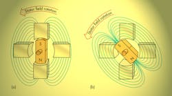
In Figure 7a, the effective stator magnetic axis is vertical, thus “grabbing” the rotor permanent magnet and aligning it as shown. In the Figure 7b sequence, the central effective axis has shifted 45° clockwise. The motor works because the stator field is rotating.
It raises another question, though: “What happens if the stator windings are excited by a more typical ac source, say sinusoidal waves generated by the electric power company?” In fact, this is how the motor is made to function as a conventional ac-powered synchronous motor. The vertical coils are powered with a cosine wave, and the horizontal coils are powered with a sine wave (both are sinusoidal; they’re merely the same waves, but shifted in phase). This stator excitation method causes the stator magnetic field to rotate at a uniform rotational speed, called the synchronous speed, which has a uniform amplitude no matter where the field may be aligned at any given moment.
The Rotating Stator Field
Figure 9 illustrates the rotating field and rotor synchronization idea. The rotating field is the basic concept surrounding ac-powered motors, and the main reason why their construction is simpler than dc motors. The field rotates at its synchronous speed (described in the equation provided later in the article). The magnetic rotor, naturally, locks onto the rotating field and spins along with it (Figs. 9a and 9b).
Figure 9c illustrates the effects of adding external load to the motor output shaft. The rotor of the synchronous motor must spin at the same rate rotational speed of the stator field. The application of external load torque, then, does not reduce speed in the conventional sense. Any speed reduction is only momentary—applying external torque causes the rotor to slow, but as the rotor position begins to lag behind the stator-field rotation, the force of attraction between the rotor and the stator fields causes the motor to develop more torque to meet the load demand.
At some point, the magnetically induced torque equals the load torque, and the motor again locks onto the rotating stator field. Subsequently, the rotor again spins at synchronous speed, albeit by a lagging in angle. Speed measurement under loaded conditions will point out this fact. The rotor under load, however, will lag by an amount called the rotor lag angle.
Increased load torque does not slow down the synchronous motor. The maximum torque developed by the motor occurs when the lag angle reaches 90°. When that occurs, the rotor drops out of synchronism and stalls. The result is a sudden increase in stator currents and potential destruction of the motor due to overheating.
The motor in the figures is a two-pole machine. The rotating stator field’s synchronous speed is determined by:
NS = (120 / NP) fL
where:
• NS is the rotating field’s synchronous speed, in rpm
• 120 is necessary to convert minutes to seconds when all magnets have two poles (120 = 2 × 60)
• NP is the number of poles in the motor (always an even number)
• fL is the line frequency (the frequency of the ac supply voltage in hertz)
Thus, the synchronous speed of the motor under discussion is 3,600 rpm using 60-Hz ac power. The same motor in Europe or Asia, where line frequency is 50 Hz, would have a synchronous speed of 3,000 rpm. Most ac rotating machines used in both home and industrial applications are four-pole designs, translating to synchronous speeds of 1,800 rpm. Induction motors, which always undergo slip, operate below the synchronous speed (e.g., 1,725 rpm at full load).
Note that our motor has four stator-pole faces because it’s a two-phase machine. Each phase has its own magnetic field, and every magnet requires two magnetic poles. However, the number of phases should not be confused with the number of apparent poles for purposes of the previous equation.
Our motor is still a two-pole machine, and its synchronous speed is 3,600 rpm in North America. It has two phases—two separate coils (one for each phase) that are displaced around the rotor in 90° increments and respectively excited by cosine and sine waves. The two phases enable rotation of the stator field. The sine and cosine waves, which have identical shapes, are merely shifted in time, or phase.
Most industrial ac motors are three-phase, though, with stator windings spaced around the motor’s periphery in 120° increments. The three excitation voltages include a sine wave for the first phase, a second voltage that’s shifted in time phase by 120°, and a third stator winding shifted by 240°. The two shifted waves have no special names, but all three are sinusoidal. The result is a stator field that rotates at a speed given by the previous equation. Two-phase motors are popular in the aerospace industry, but not so much in the industrial sector.
This file type includes high resolution graphics and schematics when applicable.
Stepper motors have found their way into countless applications. One common usage involves the positioning drives of printers that have traveling print heads. The print heads can be accurately positioned without the need for closed-loop servomechanisms or feedback transducers. The motor is merely moved from its home position to the desired position by feeding it a specific number of pulses. These applications require that the print head, or other movable member, be returned to a home position periodically to prevent loss of its reference.


