This file type includes high resolution graphics and schematics when applicable.
The October 2014 issue of Hydraulics & Pneumatics introduced the concept of pre-processing (custom-combining) of data from multiple sensors to enhance the quality of the feedback (see "Options Add Functionality to Motion Controllers"). The technique can also protect against bad feedback and sensor failures being processed by a closed-loop control algorithm. This article discusses some real-life examples that benefited from custom feedback processing.
Improving Accuracy and Fault Tolerance
Load cells are often used as feedback devices in applications that implement control mechanisms over force. They have the advantage of ruggedness and simplicity of function, and may be less expensive to incorporate in a system compared to using multiple pressure sensors to measure force. (The difference between the hydraulic-fluid pressure on either side of the piston represents the force that the piston applies to a work piece).
Another issue that can impact machine productivity is the reliability of sensor devices. By the very nature of their task, feedback sensors must be placed very close to the action to measure a motion system’s progress. In some high-shock and vibration environments, which are common in press applications, harsh operating conditions can cause sensors to fail. And sensor failure, if left undetected, can lead to wasted production, or even endanger machine operators.
A possible solution to these sensor accuracy and reliability problems is to employ redundant sensors to track the operation. Feedback accuracy can be improved by averaging sensor readings to produce a composite result that’s fed into the motion-control loop. As a result, sensor failures are able to be detected quickly and corrective action taken without affecting production if the outputs of multiple load cells monitoring the same parameters can be compared and analyzed.
But how can you gather inputs from multiple redundant sensors and process them to achieve the desired results? The key is to select a motion controller that can process data from multiple sensors before it’s used in the actual motion-control loop.
For example, engineers at Parker Hannifin’s Hydraulic Pump Div., Marysville, Ohio, faced such a challenge: They had to implement controls for an application to maintain a large amount of downward force on a 50,000-lb. metal plate to a very tight tolerance. Also, because of the critical nature of the process, it was important that the system be protected should any force sensor fail to provide the correct readings.
To provide the necessary redundancy, one load cell was attached to each of three hydraulic cylinders controlled by a single motion controller operating a single servovalve. Further, to ensure adequate application of force, four groups of three cylinders were arranged along the plate (Fig. 1). A separate motion controller and servovalve operated each cylinder.
Each load-cell output was compared to the target force, and if any of those outputs drifted beyond a target value for more than a set maximum time, that particular load cell would be eliminated from the average. The remaining two load cells’ outputs would then be averaged. The timer allows the system to filter out desired step changes in target force to avoid false indications of load cell failure. “The overall accuracy of averaging is unbelievable,” said Tim Beck, Parker engineer. “Out of 172,000 lb. of target force, the actual force readout on our HMI was fluctuating ±25 lb.”
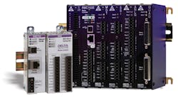
To control the hydraulics, Parker Hannifin selected the RMC150 motion controllers from Delta Computer Systems Inc. (Fig. 2, right). The controllers handle the pre-processing of data from the load cells using a feature called custom feedback, which allows the motion-control loop to use feedback from a source other than directly from the hardware input. Instead, axes defined with custom feedback obtain feedback values to be used by the control loop from an internal register. A user program that continuously monitors all of the inputs from the sensors calculates the average feedback value and assigns it to this register.
In Parker’s press application, the user program tests and averages the data from each load cell in the group of three connected to it. The resulting average is used as feedback to precisely control the force applied to the pressure plate. Averaging the load-cell readings also reduces the effect of any electrical noise in the system, which helps the control loop produce smooth outputs to the servo valve.
Besides looking at the load-cell force outputs individually to decide whether the sensor values are viable, software running on the controllers also monitors operational status information coming from the load cells. Based on that info (e.g., the load cell seems to have become unplugged or has failed), the user program running on the motion controller automatically eliminates that load cell from the next scan and issues an alarm to the machine operator.
Expanding measurement range
Hydraulic pressure sensors are designed to respond and provide readings over specific pressure ranges. Units that provide highly precise measurements, or measurements over very wide ranges, are more expensive and harder to obtain than sensors with greater measurement granularity or those designed to respond to more restricted pressure ranges. This can pose a problem for test-system developers who need to be able to apply pressure or force very tightly over a wide range. A solution to the cost and availability problems can be to employ multiple sensors of different sensitivities to measure the same pressure point, and use a pressure-control system that switches between the sensors as required by the current state of the system.
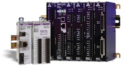
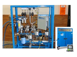
This solution was adopted by Wilson Co., Systems Div., Addison, Texas, in developing a new hydrostatic test platform called IntelliTest for use by the oil and gas industry (Fig. 3). Wilson engineers needed a controller that could switch on-the-fly between pressure-feedback devices of different sensitivity ranges, and their search brought them quickly to the RMC75 motion controller (Fig. 2, left). It may at first seem strange to use a motion controller because no visible motion occurs in this application. But an electrohydraulic motion controller excels at controlling pressure, which is the focus of the hydrostatic testing process.
Hydrostatic testing uses water to pressure test a vessel or a segment of pipe or some other specimen inside a high pressure system. “Typically we test up to 30,000 psi,” said Dave Pellerin, Wilson Company VP of Engineering, “but we can test to much higher pressures if needed.”
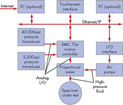
In the Wilson system, air pressure controls reciprocating pumps (intensifiers) that pressurize the water flow to the test specimen to the desired level. Compressed air at 100 psi going into each intensifier can produce 40,000 psi out of the outlet. The motion controller communicates with the intensifiers to turn them on and off via its built-in Ethernet/IP interface. It also controls the fluid pressure being applied to the specimen via a servovalve interfaced directly to its ±10-V analog output.
Pressure information is obtained from two pressure transducers, which the RMC75E (E designating Ethernet communications) switches between automatically, depending on the state of the pressure test being run. “We only need two transducers to handle the full range of 150 psi to 40,000 psi,” said Dave Pellerin. “Most of our customers want the pressure being applied to be within a 5% tolerance of reading. Typically, we use a 40,000-psi pressure transducer during the operation, which is accurate to 4.8% at 1,500 psi. But if someone wants to test at 150 psi, the 40,000 psi version wouldn’t be accurate enough. For lower pressures, we use a 5,000-psi transducer.” Figure 4 shows the transducers connected to the motion controller.
The Wilson system uses open-loop control as fluid pressure starts to build. Then, as the pressure approaches the target value, the controller switches smoothly to closed-loop control, running a custom feedback user program to switch transducers based on the pressure called for by the test.
The two applications described above demonstrate the advantages of pre-processing sensor feedback before it reaches the control-loop equation. In the end, machines become smarter, more reliable, and can produce more or better results for less money.
Bill Savela, P. E., is technical marketing and sales director at Delta Computer Systems Inc., Battle Ground, Wash. For more information, call (360) 254-8688 or visit www.deltamotion.com.
This file type includes high resolution graphics and schematics when applicable.
