Understanding hydrostatic transmissions
A hydrostatic transmission (HST) exists any time a hydraulic pump is connected to and dedicated to one or more hydraulic motors. Versatility is achieved by making either or both the pump and motor(s) variable displacement. The result is a continuously variable transmission (CVT).
An HST is preferred over shifted gear transmission in many cases because of the stepless way in which the HST’s speed ratio can be changed. Many such CVTs are manually changed, while others change automatically. A popular automatic configuration uses a manually adjusted pump displacement with a pressure compensated motor. This configuration results in the so-called “constant output power” transmission. These transmissions produce a speed-torque characteristic that is hyperbolic, and they are used primarily to prevent lugging of the prime mover. There are others, but the aim here is to concentrate on the implementation of the models.
Establishing a model
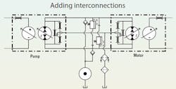
Figure 1 shows the first step in connecting Type 2 pump and motor models when configuring a hydrostatic transmission. Input torque to drive and power the pump is from some unspecified source at the left in Figure 1. Similarly, the motor output shaft is supplying power to some unspecified rotational load to the right.
The A and B Port nomenclature of the two machines is not standard in either ISO or US standards. Rather, it’s been copied from the standardized practice used with valves. In fact, I’ll sometimes refer to them as the work ports of the pump and motor, as is common with directional valves.
The A port of the pump connects to the A port of the motor, the CD ports of pump and motor are connected together, as are the B ports of the pump and motor. In this way, the output of the pump feeds and powers the motor, and the spent fluid from the B port of the motor supplies the inlet (B port) of the pump. Meanwhile, internal leakage that makes its way into the pump and motor cases is combined to also feed the pump inlet through internal leakage passages.
Real-world conditions
In a perfect world, this configuration might be practical. But it is not, for at least two reasons. First, the internal leakage that empties into the respective cases can only escape by going “backwards,” through the internal leakage paths that connect between the cases and the low pressure work ports. With no means for the case to relieve itself, the pressure in the case will be about 50% or more of the work port pressure at the moment. It could be hundreds or thousands of psi. This necessitates a high strength case and high pressure shaft seals in both the pump and motor. High pressure shaft seal technology can accommodate such pressures — at a cost, of course. However, building the outside shell of variable displacement pumps and motors to withstand such high pressures can be prohibitively expensive.
Second, the inevitable loss of fluid and temperature changes will affect the at-rest pressures of the transmission. Those pressures are uncontrolled, and the likelihood that they will become excessively high in the closed and sealed system are low. However, they certainly will become excessively low, which will result in cavitation and its attendant damage to both machines. It must be prevented by adding circuit elements that will provide the necessary pressure control.
Real-world enhancement
Figure 2 also shows the hydrostatic transmission using the Type 2 analytical models for the pump and motor, but with the enhancements that make the machine practical. The individual configurations can be seen along with their respective internal leakage paths. Leakages occur from port to port as well as from port to case drain. The supercharge pump (often called simply the charge pump) connects to both work ports of the pump-motor common connections through individual check valves.
Supercharge pressure is normally low, as hydraulic circuits go, being nominally between about 150 psi and 300 psi. As such, the pressure is only about 1/10 or 1/20 of the maximum working pressure of the transmission. The supercharge pump and check valves are intended to prevent the lower pressure side of the work ports from dropping too low. If the pressure drops below atmospheric, the destructive effects of cavitation will put the pump and motor reliability in jeopardy.
Real-world application
As the transmission does its job, the working pressures are rapidly shifting between high and low values. Consider that the transmission is being used for the propulsion system on an all-terrain vehicle as it goes up and down hills and obstructions. In climbing the hill, the A port pressure will be high, but as the apex of the hill is crossed, the vehicle starts downhill, and the pump and motor swap roles.
The energy of the descending vehicle is forced into the motor, causing it to become a pump, but its direction of rotation does not change. To absorb the energy, the pressure switches quickly and the B port pressure becomes high while the A port pressure drops to the supercharge level.
This pressure reversal causes the pump to switch to a motoring mode, so it tries to over-speed the prime mover. The result is a braking action for the vehicle. If the braking action is insufficient, and the prime mover is a diesel engine equipped with a timing change mechanism to fire the fuel injectors before top dead center, a power braking effect will slow the descending vehicle. If the prime mover is an electric motor, braking action can be achieved by over-speeding, resulting in energy flowing back into the battery. In other configurations, braking energy can be stored hydraulically in accumulators that are eventually discharged into the transmission motor to assist propulsion.
Download this article in .PDF format
Fluid conditioning
Returning to Figure 2, consider the heat exchanger and filter. Only the fluid that makes its way out of the CD ports is cooled and filtered. Depending on the volumetric efficiencies of the pump and motor, the total case drain flow will be about 5% to 20% of the transmission’s power port flow. Is this a reasonable strategy for fluid conditioning?
First, consider the cooling issue. All the case drain leakage flow has been “squeezed through” the small internal clearances at very high pressure, so it has undergone considerable heating. The flow that has gone through the displacement elements also undergoes a pressure reduction, but its energy is converted to torque and sent out the shaft. This flow is not substantially heated, so it requires little cooling.
The port-to-port leakage is another matter. It goes directly from the high pressure port to the low pressure port and is recirculated without any cooling at all. Even though this fluid is not cooled, the method is viable if the heat exchanger is sized to cool both case drain and port-to-port flow. That’s because the supercharge circuit replenishes the transmission’s low pressure side with slightly over-cooled fluid, which combines with the main power port flow.
The issue of filtering only case drain flow, on the other hand, has no absolute answers. If there are any absolutes, they are: First, get your fluid clean, and second, keep it clean. After protecting against catastrophic failures, nothing will enhance component reliability better.
Some advocates encourage placing high pressure, full flow filters in the power ports on both sides of the transmission. This provides a remarkable amount of protection. However, detractors point to high initial cost and continued maintenance. They will further argue that if the fluid has been properly cleaned, and contaminant ingression is under control, then any increase in contamination has to be internally generated, say, from component wear.
Incorporating dynamics
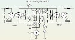
Dynamic effects are easily added to the Type 2 analytical models, shown schematically in Figure 3. In the study of machine dynamics, we are interested in changes in speeds, torques, pressures, and the like — more specifically, the factors that act to prevent instantaneous changes in them. In a hydraulic circuit, inertias of the prime mover, the pump, the output motor, and the load inertia prevent speeds from changing.
These effects are shown in Figure 3 as the curlicue symbols in the mechanical sections. Fluid compressibility and line expansion prevent pressures from changing instantaneously. Those effects are symbolized with electrical capacitors (labeled C, with appropriate subscript) in the schematic. The rule for adding dynamic effects is very simple: add inertia in each torque summation loop (pump shaft input circuit and motor shaft output circuit) and add a separate capacitance at each node in the hydraulic circuit. A node is a point where there is a pressure value different from all others. Four are shown in Figure 3, identified by the four pressure gauges.
We write six dynamic equations to study the transients in the HST: two sum the torques in the pump and motor shaft circuits, and four sum the flows at each of the four nodes in the hydraulic circuit. We would calculate about 30 or 35 different variables in the solutions to the equations. These would provide enormous insight into the operation of the transmission under any manner of dynamic changes, such as loads, displacements, prime mover speed, or any combination of these.
Deeper discussion of dynamics is beyond the scope of this column. But in the end, the Type 2 analytical models are helpful in sifting through and understanding many of the intricacies and nuances of a hydrostatic transmission.


