Hydraulic-Electric Analogies: Part 2—Adding a Variable to Positive Displacement
This file type includes high-resolution graphics and schematics when applicable.
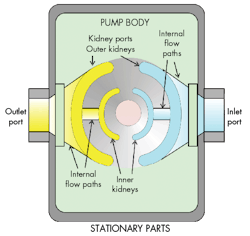
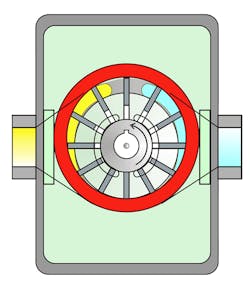
The vane pump is a positive-displacement pumping mechanism with an assembly that starts with a body containing the plumbing ports for connecting the inlet and outlet to the hydraulic system. A simplified cutaway diagram is shown in Figure 2. Four internal kidney-shaped ports are arranged in inner and outer configurations.
The two outer ports, which transfer the majority of fluid from the inlet to the outlet, are necessarily the larger pair. The inner ports carry the respective pressures of the outlet and inlet ports to the undersides of the sliding vanes and contribute a small amount of pumping action. Their main purpose is to apply some pressure on the underside of vanes to force them into the cam ring, thereby forming a seal between the inlet and outlet ports. Internal flow paths are machined or cast into the body so that all of the yellow areas have essentially the same pressure, whereas all aqua areas are at the inlet pressure.
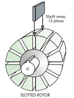
The vane pump’s moving parts consist of a slotted rotor into which rectangular vanes are inserted, one vane for each of the slots (Fig. 3). Clearances between the vanes and slots are such that a compromise is made between having the vanes freely sliding within the slots and forming a fairly high impedance (low internal leakage) path between the high- and low-pressure sides. The pump design in Figure 3 has 12 vanes, but any even or odd number of vanes can be used.
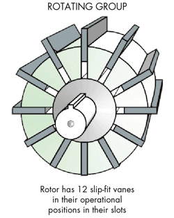
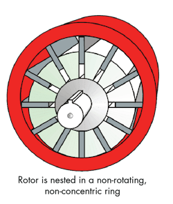
Figure 4 shows all of the vanes inserted into the rotor and the rotor assembly inserted into its cam ring. The sliding fit between the rotor slots and the vanes ensures that the vanes can move outward from centrifugal force to make positive contact with the inner periphery of the cam ring. The cam ring constrains the outward (radial) motion of the vanes while the eccentricity between it and the rotor’s center of rotation controls the pump’s displacement.
Figure 5 shows the full rotor assembly nested inside its cam ring. The ring is drawn at its most extreme upward position, which produces the maximum amount of eccentricity between the rotor’s spin center and the cam-ring center and results in maximum pump displacement.
The Moving Parts
The vane pump has three groups of moving parts in the vane pump. First, the rotor spins about the shaft center line. Second, the cam ring moves up and down to control the displacement. Third, the vanes undergo both sliding and rotating motion. Note that the cam ring does not rotate; it can only move up and down. The assembly consisting of the rotating group and the cam ring are now ready to be installed into the pump body, getting a step closer to a functioning pump.
Pumping action can be visualized with the aid of the body and rotating group, partially depicted in Figure 6. It all takes place in the volumes bounded by the rotor, the cam ring, and a pair of consecutive vanes. With the rotor spinning as indicated, look at the pair of vanes near bottom dead center, where the rotor is almost touching the cam ring. The volume trapped in the chamber between the vanes is nearly zero.
However, realizing that rotational motion is taking place, the volume will increase as the rotor drags the vanes along with it. The increased trapped volume reduces pressure within the expanding chamber, causing atmospheric pressure within the reservoir to push fluid into the chambers.
Eventually, the small chamber rotates to the top position, which has the greatest trapped volume and is filled with its maximum gulp of fluid. After crossing over top dead center, the filled chamber comes into hydraulic communication with the high-pressure outlet port. Thus, the large trapped volume undergoes an extremely rapid increase in pressure.
At that same time, the vane shown at the 12 o’clock position forms a seal to separate the high- and low-pressure ports. Thereafter, further rotation causes the volume to decrease in the chamber, and the rotor-to-vane coordinated motion, relative to the stationary cam ring, pushes the high-pressure fluid through its kidney port (yellow) and out to the hydraulic system.
The kidney ports are arranged so that all of the chambers on the left half of the rotor are at high pressure, while those on the left half are at low inlet pressure. With counter-clockwise rotation, as indicated in Figure 6, the right-hand external port is the pump inlet while the left-side port is the outlet.
Dealing with Leakage
Sealing between the high- and low-pressure sides is imperfect—and important. Internal leakage can make its way from the high-pressure side to the low-pressure side via several paths: An imperfect seal exists at the vane tip, as does clearance at the sides of the vanes, requiring a close fit in the axial direction between the rotor, vanes, and the stationary parts. Some small amount of leakage makes its way between and around the vanes and their slots through the clearance that’s needed between the ends of the rotor body and the stationary mating parts.
Much of this internal leakage finds its way into the pump body (commonly referred to as the case), shown in pale green in Figure 6. In that pump body, it must leak back into the low-pressure port to be recirculated into the pumping chambers. Thus, the pump body can reach internal pressures that approach the supply pressure.
Containing the pressurized fluid in the body requires the use of a high-pressure dynamic shaft seal. In many pump designs, a third hydraulic port is created that carries the internal leakage back to the reservoir. This greatly reduces the internal pressure and lowers the demands on the shaft seal. Modern sealing technology can eliminate external leakage from hydraulic machines if the system is properly maintained.
Taking a Position
The pumping elements in Figure 6 are shown in the maximum displacement position. The cam ring has been positioned in its maximum up position, resulting in the maximum eccentricity between the center of rotor rotation and the center of the cam ring.
If the rotor and cam ring are perfectly concentric, the displacement will be zero. If the cam ring is dropped below the concentric point, the inlet and outlet ports will be reversed, and so will the output flow without changing the direction of shaft rotation. Such pumps are variable displacement, and said to be capable of over-center operation, meaning the displacement can take on either positive or negative values.
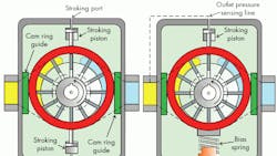
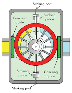
Now, though, the need arises for some external means of changing the cam-ring position so that pump output can be changed at will, or changed automatically using feedback. The stroking pistons shown in Figure 7 provide that capability.
External ports allow hydraulic access to the pistons, usually with an electrohydraulic servo or proportional valve. Electrohydraulic stroking is done by closing the loop on the cam-ring position with a position transducer, most often with a linear variable differential transformer (LVDT), not shown in Figure 7. Cam-ring guides (dark green) prevent its right-left movement.
Pressure compensation in the variable-displacement pump is easily achieved via hydraulic methods. Pressure compensation equips the pump with internal feedback that automatically reduces displacement if a threshold pressure is exceeded.
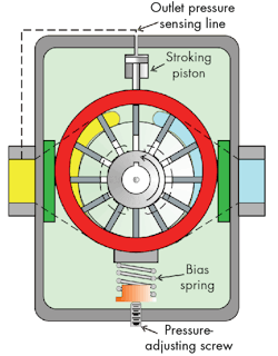
In fact, pressure-compensation pumps can be safely deadheaded; that is, the output port can be totally blocked without damaging the pump. One way to achieve pressure compensation of the vane pump is shown in Figure 8.
Here, the lower stroking piston has been replaced by a bias spring with a pre-compression adjusting screw. The upper stroking piston’s hydraulic port is connected to the outlet pressure so that the piston “senses” the outlet pressure. The bias-spring pre-compression causes an upward force on the cam ring, forcing the cam ring into the position shown when the outlet pressure is low. Under this operating condition, the pump operates like a fixed-displacement pump at max displacement and max output flow.
As the load pressure builds, the stroking piston exerts an increasing force on the top of the cam ring. At some point, the stroking piston force exceeds the pre-compression force of the spring, which automatically decreases the displacement. Blocked port pressure and deadhead pressure mean the same thing, i.e., the pressure at the outlet port under the condition of zero output flow. It is analogous to the Thevenin voltage of an electrical generator or other voltage source.
The preceding figures on vane pumps are not necessarily depicting actual construction practice of such machines. Instead, they show the principles of operation. For example, pressure-compensated vane pumps do not use physical stroking pistons. A less-costly method is to rotate the kidney ports slightly in the direction shaft of rotation, counter-clockwise. A tremendous force acts on the inside of the cam ring at high pressures, upwards of tens of thousands of pounds in large pumps at high pressures.
By rotating the kidneys ever so slightly, a component of force emerges in the down direction. That force is used to act against the bias spring and force the cam ring downward in the face of high outlet pressures. Therefore, no stroking piston is needed. And eliminating the stroking piston can significantly reduce the size of the pump body. Many other practical construction details exceed the scope of this brief look at electric and hydraulic analogies and principles of operation.
Looking for parts? Go to SourceESB.
