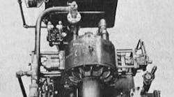
These power packages, which supply oil to the cylinders, are connected electrically so that they operate simultaneously.
To ensure synchronization of the jack cylinders, it was decided to power each one from a separate variable and reversible volume pump. The use of such pumps, in addition to offering high volumetric efficiency, allows the necessary incremental adjustment of the volume delivered in order to obtain synchronization.
The variable and reversible volume feature of the pumps offers the additional advantage of permitting smooth acceleration and deceleration of the cylinders without shock. This is accomplished in the following way.
Referring to the circuit drawing, the pumps are normally on negative or idle stroke so that the actual pressure port becomes a suction port and oil is pulled from the tank through the check valve, and circulates back to tank at zero pressure. Pressing the “up” button energizes solenoid A-1 in the main pilot valve, and B-1 in the control valve for the double acting pump stroking cylinder. The 2 inch, four-way two position valve, which provides directional control of the cylinders, shifts to the “up” position; the pumps are stroked from full negative to full work stroke which builds up the oil delivery slowly to accelerate the car. Releasing the button de-energizes B-1, but not A-1, and the pump is stroked back to negative or idle position, decelerating the car to a stop.
To lower the car, which operation was to be carried out at the same speed as dumping, it is obvious that the pumps would have to be placed on something less than full stroke, for they are now delivering to the rod end of the cylinders. As a result of some other considerations, the rod end area was finally set at one half the total piston area, thus calling for the pumps to be placed on only half working stroke for lowering. An actual volumetric capacity of the pumps is 44gpm.
With the pumps on idle stroke after dumping, the “down” button is pushed energizing A-2, B-1, and C-1. The main 2 inch, four way directional control valve now shifts to the “down” position with the pumps once again being stroked from full negative to work stroke for accelerating the car. However, in this case a second stroke positioning cylinder is brought into play through pilot valve C-1, which ahs been energized, so that the pumps can move only to half working stroke.
No Valve Reversal Under Pressure
When the car is completely lowered, the jack cylinders have additional stroke, which allows the hooks on the rods to engage the cam pedestals so that the cylinders are pivoted away from the track to provide adequate clearance for the locomotive and cars.
Releasing the “down” button deenergizes A-2, B-1, and C-1, returning the pumps to idle position.
It can be seen, then, that the main 2 inch, four-way valve never reverses under pressure, because the pumps are put on delivery stroke only when the “up” or “down” button is contacted. In this way, hydraulic shock of flow reversal is prevented.
It is interesting to note that the action of the variable volume circuits. Most such circuits use a variable volume pump to give large volume, large pressure rapid advance, and then as pressure builds up the pump shifts to a short stroke, low volume high-pressure position. During idling, the pump is by-passed to circulate at zero pressure. In the dump car circuit, the pumps are stroked in reverse for idling and are put on full stroke at maximum pressure for the working portion of the cycle.
To provide pilot pressure for stroking the pumps and main valve, each unit incorporates a 3 gmp gear pump operating at 200 psi. A pressure switch in each of these pilot circuits functions as a safety device to prevent the control circuit from functioning unless pilot pressure is established. These switches tie in with the main motor starters so that the main pump motors will start only when pilot pressure has been developed.
Protection is also offered when shutting down in that the main motors stop first and, through the use of a timer, the pilot pump motors will shut down afterwards. Note also the spring loaded check valves on the exhausts of the pilot valves, which provide a 10psi back pressure. These were inserted to make certain that the pilot lines would always be preloaded, avoiding any delay in response of the controls.
The counterbalance valves in the lines to the jack cylinder are provided for positive operation should a full or partially loaded car need to be lowered for any reason, and to prevent over-running of the car due to a sudden shift of the load during dumping.


