Troubleshooting Challenge: Drill Rig’s Top Drive Drops Uncontrollably
This file type includes high-resolution graphics and schematics when applicable.
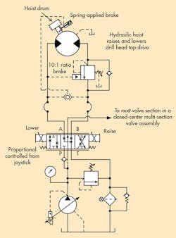
A 65-ft.-high drill rig, mounted on a freshwater barge, was allowing its top drive head to drop uncontrollably. The circuit controlling this function shows (see illustration) both a brake (counterbalance) valve and a hydraulically controlled mechanical brake on the hoist function. The systems’ power unit was mounted close to the deck, with its A and B line hoses going up to top drive’s hydraulic motor. The brake and shuttle valve were plumbed close to the motor, which lifted and lowered the drill drive head.
When the operator first started the unit and commanded the top drive head to be lowered, it dropped uncontrollably, damaging the drill bit or buckling the drill string (pipe). The operator also heard a “ratcheting noise,” as if the mechanical brakes were attempting to grab. This problem also occurred after the hoist was raised and locked into place with the mechanical brake, and not operated for about an hour.
The operator found that he could raise the top drive head first and then command it to lower, and it seemed to work okay, but it started jerking for a few seconds. No oil leaks were visible in any of the plumbing from the motor down to the directional valve. What do you think was causing the erratic operation?
Find the Solution
Think you know the answer to this month’s problem? Submit your solution by emailing [email protected]. All correct solutions submitted by Feb. 3, 2017, will be entered into a random drawing for a $50 gift card. The winner will be notified, and his or her name will be printed in a future issue. Only one gift card will be awarded to any participant within a calendar year.
Congratulations to John Janesko, of Beckwood Press Co., St Louis, who correctly answered last month’s puzzle. A $50 gift card is in the mail to him.
Solution to Last Month’s Challenge: Drilling Barge Has Unstable Steering Problem
The barge steering system that moved as water currents changed should have maintained its position when using Sun Hydraulics’ counterbalance valves. However, choosing a proportional valve with a blocked center spool was the source of the problem.
Because sliding spools typically have their pressure port exposed to A and B ports, leakage to these ports usually builds to roughly half of system pressure. With both A and B ports pressurized, the external signal lines to the counterbalance valves cause the valves to open, allowing the cylinder to float in either direction.
The solution called for using a float-center proportional valve, which allows both A and B ports to drain to tank to keep the Sun counterbalance valves closed.


