Hydraulic-Electric Analogies: Evolution of Hydrostatic Transmission Schematics
Download this article in PDF format.
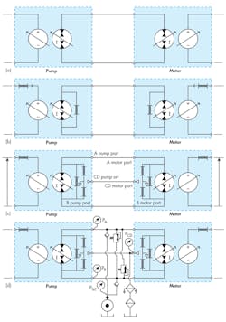
Evolution, in this context, does not mean changes in a hydrostatic transmission over time. Rather, it is the evolution from a primitive and simplistic ideal depiction to a more detailed and practical Type 2 model. The Type 2 model more closely represents a real-world hydrostatic transmission. This evolution is depicted in Fig. 1. Each stage of evolution has its place in hydraulic design and analysis.
Figure 1(a) is the simplest depiction, which shows both the pump and the motor in their ideal symbology. It explains the principles of the hydrostatic transmission. The pump symbol is on the left and has the counter-torque generator, which implies that loading effects at the pump are universal. The bidirectional pump-motor symbol suggests positive-displacement pumping action. The ideal motor uses the universal, bidirectional pump-motor symbol to characterize the flow-absorbing action of the motor displacement mechanism while the mechanical part of the circuit depicts the torque generation of the output motor.
The universal, bidirectional pump-motor symbol is often used in hydrostatic transmission schematics because in dynamic uses, the pump and motor are continuously swapping their functions. For example, if there is a substantial inertia load on the motor, while accelerating, the pump as energy stored in the inertia puts power into the motor shaft, causing it to function as a pump temporarily.
The pump has to operate as a motor, absorbing hydraulic power and putting energy into the prime mover. If the prime mover is an electric motor, either ac or dc, it can put that energy back onto the electrical grid and result in very efficient operation. If the prime mover is an engine, the engine offers some resistance and functions as a brake. These effects can be explained with the Type 0 schematic symbology. However, losses and inefficiencies cannot.
1. The illustration above shows four different stages in model evolution of the hydrostatic transmission from simple ideal pump and motor (Type 0) to characterization of multiple internal leakage paths (Type 2), which is required to help in understanding the need for the fluid conditioning peripherals in (d).
A bit more practical depiction is the Type models for the pump and motor in Fig. 1(b). Although not a complete characterization, it does account for friction in the mechanical circuit and a port-to-port leakage in both the pump and motor. Mechanical friction accounts for the mechanical inefficiency, and the internal leakage accounts for volumetric inefficiency. This model can be useful for sizing and verifying the suitability of the pump and motor to meet some targeted input and output speeds, torques and powers. It can even be used for dynamic simulations, but can only evaluate the differential hydrostatic transmission pressure. Gauge pressures cannot be evaluated with the Type 1 models.
Type 2 models are required to evaluate the case pressures because of the internal leakage paths between the power ports and case drain ports. The schematic of Fig. 1(c) takes into account the port-to-case drain leakage as well as the port-to-port internal leakages. This figure offers an important means of making the transition to the complete, practical schematic of Fig. 1(d). All of the models are useful but are limited to giving details only about the transmission differential pressure. Figure 1(d) allows the analysis and tracking of the gauge pressures of the case drain and the two power lines.
The Fluid Conditioning
The components in the center of the figure are generally referred to as the fluid conditioning circuit, but they are more than that because they also include the supercharge pump. The circular bull’s-eye symbol, near the bottom of Fig. 1(d), is the constant-pressure supercharge—more commonly called the charge pump—that provides fluid flow to make up for internal leakage losses and prevents cavitation in the pump or motor.
The charge pump is normally a small gear pump with pressure regulated by a relief valve. The regulated pressure is usually between about 100 psi (7 bar) and 300 psi (21 bar). A mathematical analysis of the circuit would show that the charge pump has to provide flow only to the extent of the internal leakage from the pump plus the motor. The charge pump flow capacity, therefore, needs only to have a flow capacity that is about 10% to 20% of full flow capacity of the main power transmitting pump and motor.
Figure 1(d) shows both the pump and motor to be variable displacement. They needn’t be in all cases. Many hydrostatic transmissions are constructed with only the pump having variable displacement. It’s very rare that only the motor is variable displacement.
The purpose of the fluid conditioning circuitry is at least threefold:
1. To prevent cavitation in the low-pressure side of the hydrostatic transmission power lines.
2. To provide cooling to prevent premature degradation of the fluid from excessive temperature.
3. To provide filtration to keep the fluid clean.
Cavitation Prevention
Cavitation prevention (perhaps cavitation protection would be more accurate) is wrapped up in the low-pressure, constant-pressure, low-flow charge pump, depicted as the circular bull’s-eye symbol in Fig. 1(d). Its output is directed through two check valves, one to each side of the transmission’s power lines. If either power line should fall below the constant charge pressure, the associated check valve will open and allow supercharged fluid to enter into that line.
The low-pressure side of the transmission is always starved for fluid, making it ripe for cavitation. This can be seen by examining the positive-displacement process of both the main pump and the motor. Of all the flow displaced by the ideal pump, a portion of it, perhaps as much as 5% to 10%, never reaches the power output port because of internal leakage paths. In complementary manner, of all the flow entering the power input port of the motor, as much as 5% or 10% will not reach the motor’s displacement elements because of the internal leakage paths inside the motor.
Thus, the volume of fluid leaving the motor that flows back into the pump is insufficient to meet the inlet demands of the main pump. This would be disastrous and damaging. However, the lowered pressure due to starvation on the low-pressure side allows the respective check valve to open, and the charge pump makes up for any flow deficiency on the low-pressure side caused by internal leakages in both the pump and motor. As stated earlier, the charge pump needs only sufficient output to make up for internal leakage.
There are also two relief valves connected back-to-back, that is, one relief valve limits pressure when the A-side is high and another limits the pressure when the B-side is high. Note, however, that the outlets of the relief valves are not connected to the tank. Instead, they are connected to the opposite power lines. This, too, is a cavitation prevention ploy. If the relief valves drained to tank, excessive pressure on the high-pressure side would cause a huge amount of fluid to bypass the motor, massively starving the low-pressure side. This would cause cavitation in both the pump and the motor.
Cooling the Fluid
The effects of friction and its resulting heat generation were discussed in a previous installment, where the need for cooling devices in both electrical and hydraulic devices was described. The internal leakages in the pump and motor are prime examples of self-heating elements. The internal leakages pass through tiny clearances inside the pump and motor. All the power that is created by the pressure times the leakage flow is converted to heat and is imparted to the fluid itself. The higher the pressure and the higher the flow, the greater the temperature rise is in the fluid. It is immediate.
The intense pressure squeezing fluid molecules through the narrow paths causes the fluid temperature to rise. All the flow leaving the case drain ports is the consequence of frictional heating. To deal with this real phenomenon, the pump and motor case drain flow are combined and the sum of the two is made to pass through a heat exchanger before returning to the reservoir. The heat exchanger carries the total case drain leakages from both the pump and the motor back to tank.
Filtration of the Fluid
Fluid filtration also takes place with the combined case drain flows in their return to tank. Some designers prefer to put three filters in the system, one in each of the transmission power lines and another in the case drain return as shown in Fig. 1(d). Objections to this very safe kind of hydraulic system design are cost of the system, which requires two high flow, expensive high-pressure filters in addition to the one low-pressure return line filter. In addition to the cost, there is always power lost in the filter, and the elements need to be maintained according to manufacturers’ recommendations.


