Hydraulics Power New Digger Derrick to Higher Levels
Download this article as a .PDF
Although utilities in new residential neighborhoods generally are buried underground for aesthetic reasons, utility poles with suspended wires still are used extensively in commercial, industrial, and rural areas. In these applications, above-ground poles and wires are much faster and less expensive to install than underground lines.
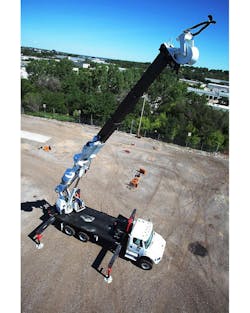
Machines known as digger derricks bore holes into the ground for the poles and place them into the holes. Digger derricks are similar to truck-mounted cranes but are designed specifically with powerful hydraulics that position the boom and rotate the auger, as well as boom-mounted grapples to handle the poles.
Although a truck-mounted crane equipped with an auger attachment also can be used for this purpose, it requires a certified crane operator and is not tailor-made for digging operations. A machine designed specifically as a digger derrick provides better digging ability. It also can incorporate special features to enhance performance and make the operator’s job easier, including systems that improve the ability to manage side loads and controls that can be operated either from the machine’s console or with a remote device.
Elliott Equipment Co., Omaha, manufactures more than 50 models of truck-mounted cranes and aerial work platforms with dozens of custom features and options. The company’s digger derrick line is designed specifically for utility transmission line construction and maintenance. The heavy-duty D105 is Elliott’s first digger derrick that meets ANSI A10.31 specifications for digger derricks.
Terry Radenslaben, product engineering development manager, says, “We have done a considerable amount of research on what operators want in a machine. We chose an operator-friendly control design, and we optimized our boom and lower assembly for digging radius, lifting power at radius, and power out of the hole at radius.” Elliott engineers also designed the unit to fit on a fully road-legal 58,000 lb. GVWR 6 x 6 tandem-axle chassis for ease of on-road or off-road transport. The machine’s six-wheel drive and compact size give it maneuverability on the unimproved roads and rights-of-way where transmission line work frequently is performed.
Hydraulic Power
The hydraulic power unit (HPU) that provides power for all of the machine’s hydraulic functions uses a variable-displacement piston pump with a 133 cc/rev maximum displacement. Driven by the vehicle’s PTO, it provides 72 gpm at 4800 psi and is rated for 6,000 psi.
A 6.0 in.3 gerotor motor with a 36:1 ratio planetary gearbox powers the turret swing drive, which allows 360-deg. continuous rotation. This flexibility helps the operator minimize the need to reposition the machine, especially when working in tight quarters. A standard 6-port hydraulic swivel maintains fluid flow to the drive throughout the rotation.
Boom Design and Functions
The D105 features a four-section proportional steel boom that extends from its 28 ft., 6 in.-retracted length to a maximum length of 95 ft. for a 107-ft. maximum tip height. At the tip is one upper sheave, with two lower sheaves for reeving up to five parts of load line. Mounted at the base of the boom is a winch that provides a single-line pull of 12,000 lb and is driven by a two-speed piston motor. The motor has a 68 cc displacement in low-speed mode and 30 cc in high-speed mode, driving the winch through a 48:1 ratio planetary reducer.
A double-acting long-stroke hydraulic cylinder with a 7.50-in. bore and 6.00-in. diameter rod provides smooth and stable boom elevation. A counterbalance valve prevents the boom from falling in case of hose failure. Boom extension is provided by a two-stage cylinder attached to the largest boom section, with a proportional cable extension system driving the outermost boom sections. The cylinder’s larger bore is 5.38 in. with a 4.64 in diameter rod, while its smaller bore is 3.63 in. with a 3.00 in. diameter rod.
A Powerful Auger
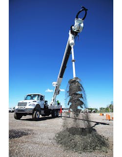
An essential component of the machine’s dual purpose design is its high-torque (20,000 lb.-ft.) auger, which can be operated at two spin speeds. A low speed (35 rpm) provides high torque for digging, while a high speed (80 rpm) can be used to quickly fling dirt from the auger. This eliminates time-consuming manual scraping and improves productivity compared to a conventional crane-mounted auger.
Designers used a two-speed variable displacement piston motor with minimum and maximum swashplate settings to achieve both the low-torque and high-speed requirements. The motor requires up to 55 gpm flow with 4,600 psi pressure. It is equipped with a solenoid coil that defaults to the low-speed, high-torque setting. When powered, the solenoid shifts to the high-speed, low-torque setting.
The auger is raised to its stowed position along the boom or lowered to be deployed by using the digger motor in conjunction with a rope connected to the stow bracket. The rope is wrapped around the shaft of the digger bit and either raises the mechanism into place or lowers it, depending on the digger motor’s direction of rotation. When it is in the stowed position, a latch driven by a 1½-in. bore hydraulic cylinder closes underneath it to secure it in the bracket.
The boom-mounted auger has a digging radius of up to 41 ft. and a digging depth of up to 16 ft., with the ability to handle augers up to 48 in. diameter. An auger bit up to 36 in. in diameter can be stowed on the side of the boom for transport. Actual pole diameters generally are slightly smaller than the auger, with taller poles requiring larger diameter bases.
After the auger has created the hole, the operator deploys a pole claw (sometimes called a pole grab or grapple) to lift the pole and position it in the hole. The pole claw has two functions: its arms open and close to hold the pole, and it also tilts to hold the pole in a vertical position regardless of boom angle. It also incorporates a pole guide. A single 2½-in. bore cylinder performs the open/close function, while a pair of 2½-in. bore cylinders performs the tilt function. There are quick-disconnects in the line to the pole claw cylinders for easy removal.
Other Features
To control the side loads encountered in digger derrick operation, Elliott replaced Glide Swing—a feature that provides a smooth swing, which is preferred in standard crane applications—with Side Load Protection. This is accomplished by piloting off the brake on the swing drive during digging operations but including sequence valves in the motor circuit. This allows the system to hold a set side load-induced pressure, then relieve smoothly but hold again as soon as the pressure drops. Radenslaben says operators feel this feature makes their jobs easier than using a crane. He explains that this approach works more smoothly and consistently for side load protection than either the gearbox brake or counterbalance valves typically used to hold rotation in crane applications.
The boom and digger functions are controlled by a pilot control valve actuated by hydraulic joysticks. Pole claw and outrigger functions are controlled by on-off solenoid valves. Boom and digger functions can be operated from the control console or from any convenient location with a portable radio remote control. The remote control also displays load information such as load, capacity, boom length, and radius at the transmitter to keep the operator informed at whatever location the machine is being operated from.
The machine has two sets of down-and-out over-frame outriggers with a 20-ft. span. They are configured for full-span or mid-span operation. Their horizontal sections are driven by hydraulic cylinders having a 2.50-in., bore and 2.50-in. rod diameter, and 76-in. stroke. Vertical sections are driven by cylinders with a 4.40-in. bore and 2.50-in. rod, with a 27-in. stroke. For work areas that are tight or unusually shaped, the outriggers can be extended to different lengths on opposite sides. The machine’s control system then senses the outrigger positions and allows full capacity on the side where the outriggers are fully extended while preventing the turret from swinging over the side where the outriggers are partially or fully retracted.
All cylinders are made with micro-honed cylinder tubing, chrome shafts, top-grade packing, and protective rod wipers. All load-holding cylinders are fitted with cylinder-mounted holding valves.
About the Author

Leaders relevant to this article:


