Download this article as a .PDF
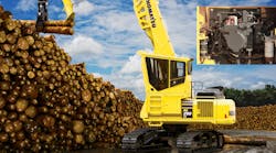
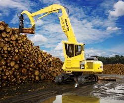
Logging equipment has to be tough and reliable to deliver productivity under demanding conditions. Hydraulics are used extensively to meet these requirements in the new Komatsu PC290LL-11, the latest addition to the company’s line of log loaders. These machines sort logs that have been cut, stack them into piles, and load them onto trucks.
Powered by a 196-hp Komatsu SAA6D107E-3 diesel engine that meets stringent EPA Tier 4 standards, the machine is available in either a live-heel log loader configuration with a 40-ft. reach or a road builder configuration with a 34-ft. reach. Log loader and roadbuilder operating weights are 40,700 kg (89,730) lb and 37,300 kg (82,240) lb, respectively.
Tandem Pumps Power Multiple Functions
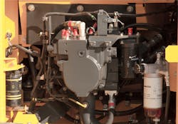
The heart of the machine’s hydraulic system contains two variable-displacement piston pumps. Pump displacement has been increased over previous models to provide greater flow output and ensure operation at the most efficient engine speed. Each pump has a maximum output of 65 gpm (245 lpm) for a total maximum flow of 490 lpm (130 gpm).
The pumps’ displacement is controlled by load-sensing pressure, in which the load-induced pressure is sensed, and pump flow is adjusted by appropriate valves to maintain a constant pressure drop—and, therefore, constant flow. In addition, electronic proportional control solenoids provide load-sensing and horsepower control.
Each of the log loader’s tracks is driven by a variable-displacement piston motor powered by each main pump. Each hydraulic motor has a maximum displacement of 182.4 cm3/rev (11.13 in3/rev) and drives a planetary gearbox, which reduces rotational speed and increase torque. The final drive generates 64,250 lb of drawbar pull. By pairing the variable-displacement motors and pumps, Komatsu’s machines can achieve three travel speeds (low, medium, and high) instead of the more common two. This is accomplished by changing motor displacement and controlling pump displacement electronically.
Hydraulic power for the swing function is provided by a bent-axis piston motor. Its theoretical displacement is 167.5 cm3/rev (10.22 in.3/rev), which provides a swing speed of 9.4 rpm and maximum torque of 10,949 m-kg (75,902 lb-ft).
More Hydraulic Functions
The main pump drives many other machine functions, including the boom, arm, and heel or bucket circuits. The boom cylinder has a 150-mm (5.9-in.) bore and 1247-mm (49-in.) stroke, the arm cylinder has a 185 mm (7.28 in.) bore and 1,421 mm (60-in.) stroke, and the heel cylinder has a 140-mm (5.5-in.) bore and 1,063 mm (41.85-in.) stroke. The heel, used on many boom type loaders, assists in handling the logs by protecting the boom and controlling the end of the log. The PC290LL-11 has a live heel, as opposed to the fixed heel used on some machines. The live heel is operated by a separate hydraulic cylinder for increased control in positioning the log.
Inside the cab, low-profile pilot proportional control (PPC) levers let the operator control the boom, arm, and heel functions. Thumb-actuated electroproportional control sliding buttons give the operator smoother and more precise control of attachments than would be possible with hydraulic pilot controls.
Komatsu designed and manufactured the major hydraulic components used in the machine, including pumps, motors, control valves, and cylinders. The hydraulic system also includes a wide-fin oil cooler, high-pressure in-line filters, and hydraulic track adjusters. In addition to the hydraulics, says Senior Service Engineer Joe Loeffler of Komatsu America Corp., says, the engine and most major components are designed and manufactured internally by Komatsu, to help achieve Komatsu Harmony. He says this creates a harmony of components that are designed specifically to work with each other, allowing the machine to fulfill the customer’s production needs in almost every application, “whether it be a work horse, a fuel saver, or a little of both.”
Electrohydraulics Improve Control
The machine’s hydraulics are controlled by Komatsu’s HydrauMind (Hydraulic Mechanical Intelligence) system, a closed-center system with load-sensing valves and pressure-compensation valves. The system enhances energy efficiency and operation with simple electronic controls that can be adjusted to match work conditions. Unlike typical open-center systems, HydrauMind’s closed-center design combined with load sensing matches pump output to work conditions automatically. Six working modes match engine speed and pump output to load conditions based on the positions of operator controls. Those modes are:
- P Mode – Power Mode (heavy-load operations)
- E Mode – Economy Mode (emphasis on fuel economy)
- L Mode – Lifting Mode (fine control operations; increased pressure combined with lower engine speed)
- B Mode – Breaker Mode (for breaker operation or other single-acting attachments)
- ATT/P Mode – Attachment Power Mode (operation of double-acting-way attachments, such as crushers)
- ATT/E Mode – Attachment Economy Mode (operation of double-acting attachments, such as crushers, with emphasis on fuel economy)
Another feature that improves productivity is the machine’s Power Maximizing system. “The system is a short-term Power Boost,” Loeffler explains. “When the operator presses and holds the ‘One Touch Power Maximizer’ button, system relief pressure increases by 7% and engine speed increases by 17% for increased flow at rated pressure for up to 8.5 seconds. This function is useful in situations where the operator may hit patches of higher density or heavier material that would generally slow or stall the hydraulic system at standard relief pressure and flow.
Hydraulic Turbo Control Improves Fuel Economy
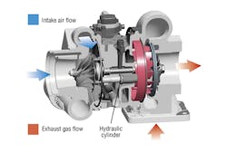
Komatsu America also uses hydraulics in its Variable Geometry Turbocharger (VGT) to improving engine performance directly. Standard turbochargers use a turbine in the engine’s exhaust stream to capture the kinetic energy of exhaust gas and convert it to rotational power. This rotational power is then transmitted through a shaft to a turbofan, which pressurizes (charges) air in the engine’s intake manifold.
A limitation of standard turbochargers is poor low-speed performance. At low engine speeds, the stream of exhaust gas is not strong enough to provide sufficient charging of the intake air. However, Komatsu’s Variable Geometry Turbocharger uses a hydraulic cylinder to vary the effective area of the exhaust turbine. This causes the turbofan to rotate fast enough to charge the intake air at lower engine speeds.
The hydraulic cylinder controls the axial position of the exhaust turbine. At high engine speeds, the cylinder is fully retracted, which exposes the full width of the turbine to the stream of exhaust. However, at lower engine speeds, a directional control valve—commanded by the engine’s electronic control system—causes the cylinder to extend. This removes a portion of the turbine (the right side, as shown in the drawing) out of the exhaust flow. The narrower flow path of the exhaust passage increases laminar velocity of the exhaust flow, which causes the turbine and turbofan to rotate faster from lower exhaust flow. The result is cleaner exhaust and higher fuel economy without sacrificing engine performance.
