By Jack L. Johnson, P. E.
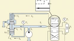
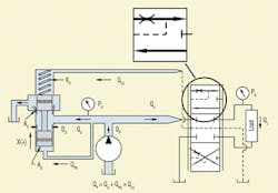
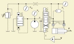
To conclude our discussion of unloading valves, consider that Figure 5 adds a 4-way spool to the valve drawing of Figure 3 from last month. Note that the spool has two additional ports. They switch the sense line so that the spring end of the unloader spool (often called the compensator spool, due to its flow regulation function) “listens to” the correct valve work port, regardless of the direction that the 4-way spool has been shifted.
Note further that when the 4-way spool is centered, the spring side of the compensator spool is connected to tank. Thus, the pressure required to overcome pre-compression of the bias spring is the pressure at which the pump is unloaded. This fact argues for lower pre-compression or a softer spring. Good control, however, argues for just the opposite.
Sensing load pressure
The switching of the load sense line needs a bit more explanation. In expansion of the straight-through porting envelope of Figure 5, the sense line is indicated with dashed lines. The configuration shows that the sensing is specifically ported internal to the valve. This provides sensing downstream of the powered land orifice — that is, downstream of the small internal orifice drawn on the accompanying spool blow up.
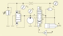
Figure 6 is an alternate method for sensing load pressure. Instead of using the 4-way spool to switch the sense line, a shuttle valve is used to sense the higher of two cylinder pressures. Some additions are needed to make this circuit practical, however this works in many cases.
The fallacy comes in the case of over-running loads. Conventional wisdom assumes the powered end of the cylinder (be it rod end or cap end), is at the higher pressure. However, an over-running load can occur, causing the unpowered (meter-out) land pressure to be higher. In that case, the sense line to the spring cavity does not sense the pressure drop across the powered land. Instead, it has some other pressure which is a complex function of just about everything in the circuit.
The circuit’s behavior is difficult to predict and can result in sudden changes in load speed. The circuit is workable if loads behave according to conventional wisdom, except for another minor glitch. With the spool centered, if a load is on, say, the cap end of a cylinder (as would be encountered on the lift cylinder of a front end loader), then that is the pressure sent back to the unloader spool spring cavity. This becomes the pressure at which the pump is unloaded when the 4-way spool is centered.
This hardly makes for efficient operation. To combat the problem, valve designers are forced to put a special land on the spool that routes the load-sense line to tank with the 4-way spool centered, Figure 7.
The problem with the circuit of Figure 6 is best seen by considering what happens when a load is on the cylinder with the valve centered. An example would be a front end loader with the bucket raised, and the operator wants to keep the bucket raised. In this case, the shuttle valve will shift to connect the high pressure to the spring cavity of the unloader spool, and the pump will be unloaded at high pressure. This is hardly the efficiency we want.
For the unloader to do its job at low pressure, we must provide a special land, or slot, in the 4-way spool that drains the load-sense line. This is called a sense dump line, or sense relief line. The necessary circuitry and changes to the valve are shown in Figure 7. Now, with the 4-way spool centered, the unloading pressure is set only by the unloader’s bias spring and its amount of precompression. However a new glitch comes up with this circuit change.
Load sensing and load holding
Again consider that some load is on the cylinder that causes a high pressure in the cap end. With the shuttle valve shifted to route that pressure into the load-sense line, and with the 4-way spool centered, a flow path to tank exists through the sense dump line. This will cause the load to settle at a rate determined by several factors; most importantly, the amount of restriction in the sense dump line. With multiple 4-way sections in the stack, the sense dump restriction increases. However, in most applications, the amount of load settling is objectionable.
To positively hold the load with the unloader valve, we need pilot-operated check valves in the cylinder circuit. The changes are shown in Figure 8. Recall from previous discussions of the more conventional open-center valves that each 4-way spool was accompanied by a transition check valve. The purpose was to prevent a sudden drop in cylinder loads when a 4-way spool was shifted. It served no purpose regarding the ability to prevent load settling from spool-to-bore clearance leakage. All spool valves suffer from some degree of clearance leakage, and counterbalance or pilot-operated check valves — with their metal-to-metal seal — are required if load holding is critical.
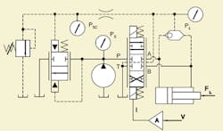
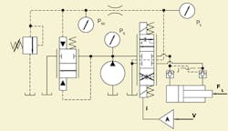
Figure 9 is included to make several points. First, the shuttle valve load sense logic is not used. Instead, the spool-switched load sense that was introduced earlier is used. Second, the small V-shapes on the powered land flow arrows in the valve symbol indicate the natural restrictiveness of the land. Third, the load-sense line is taken off the work port side of the envelope, and the internal dashed lines indicate that sensing is made downstream of the powered land restriction. In other words, the load pressure is being sensed, which is exactly what should be sensed. Also, pilot-operated check valves are included but may not be needed if load motion is purely horizontal.
Additional functionality
The configuration in Figure 9, with its spool-switched sense ports and lands, is fully workable and useful as a single-spool valve. But most mobile equipment valves have several functions in the stack. Figure 6 is included to aid in understanding the features that must be added to the valve assembly when more than one 4-way section is in the stack. All the features relate to the need for getting the correct load pressure back to the spring cavity of the unloader spool while accommodating efficient unloading when all spools are centered. Also, Figure 6 shows the single-function unloader valve in conventional ISO symbols. However, the circuit is not practical unless it can accommodate more than one 4-way spool in the stack.
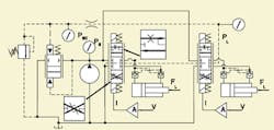
A way to accommodate multiple 4-way functions is shown in Figure 10. This valve has two 4-way spools but uses the spool-switched sense line concept from Figure 9, and there is no shuttle valve. Note that the sense line is routed through all the spools and down the center of the 4-way stack, beginning with the spool that is farthest down the stack. When that function is shifted, the spool-sensed switching cuts off the pressure sensing of all functions closer to the unloader spool that may be shifted. This design is said to have stack position compensator priority. In other words, whether or not a spool is pressure compensated depends on its position in the stack.
For brevity, another variation, in which the priority logic is reversed, is not shown. That is, by redrawing the 4-way envelopes (see the blow ups in Figure 10) and threading the center sense line in the opposite direction, the spool closest to the unloader will become a priority. In fact, this is the more common means of design and construction, but the emphasis here is that such concepts needn’t be seen as unchangeable or lacking alternatives.
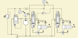
Figure 11 shows the circuitry that can change the load-sense logic. A shuttle valve connects the two sense ports of the two 4-way valves. The unloader spool is now motivated, not by a 4-way’s position in the stack but by the higher load pressure. If more than two 4-way spools are in the stack, the highest pressure priority can be maintained by connecting shuttles in binary fashion. That is, each pair of 4-way spools is connected to its own shuttle. Their outputs are paired with one other shuttle, and that output is then paired with one other pair, until they are “Christmas treed” together until a single output feeds back to the unloader spool. In this manner, two spools require one shuttle, four spools require three shuttle valves, eight spools require seven shuttle valves, and so on.
Simultaneous operations
As is the case with more conventional open-center valves, simultaneous operation of several functions can become complex. System designers are faced with complex mathematical configurations, many of which can be solved only with simulation methods and computers. Operators can have difficulty in training because the behavior of the controls can depend on the cylinder loading and the relative loading between cylinders.
None of these problems is solved when going from conventional open-center designs to the unloader/compensator design. In fact, simultaneous operation of multiple functions can be even more difficult with unloader designs, analytically speaking, and operators can be surprised by sudden changes in load speeds. This is especially true when there is disparity between loads, and the 4-way valves are shifted one after the other.
All of the unloader/compensator designs shown until now provide for predictable output flow or actuator speed when only one function is shifted. To help make the point, here is a brief recap of single-function operation: First, the unloader compensator adjusts in an attempt to keep the load flow or speed more dependent on the amount of shift in the 4-way spool than on the load. Second, pump pressure rises only enough to support that operation, assuming the pump is not undersized. Third, the action of the compensator function eliminates the apparent, load-dependent dead zone of the conventional open-center valves. Fourth, all 4-way stacks are configured for parallel operation, not series operation. To my knowledge, this the only configuration that has been commercially viable.
However, when more than one 4-way spool is shifted, predictability can be problematic. For example, what happens when a heavily loaded spool is shifted, and after its load is set into motion, a second spool is shifted, but it has a very low load? In fact, consider that the second load is so small that it steals the flow from the high-pressure load. Flow stealing calls for a reduction in pressure at the pump. Will it drop until the high pressure load stalls, which would argue in favor of a rising pump pressure? Or will the system reach some new condition of equilibrium where both loads are moving at some “compromised” speed? Or maybe the system will break into oscillation and chatter as pressure rises and falls. Will the high pressure load drop?
These questions can be answered for specific cases but are difficult to answer in a general sense. The answers are best predicted by having good, detailed mathematical models of the valves that can be analyzed in a simulation program.
Unfortunately, no standard test methods exist to evaluate all the parameters needed for detailed mathematical modeling of dynamic responses. The critical item to evaluate is the dynamic impedance of the sense lines, which have earned total silence on all valve testing standards. Sense lines are always small and often long, meaning that they have modes of operation with laminar flow. But they are also subject to large differential pressures, which means they can at times have turbulent flow.
In the next issue we’ll discuss a logical extension of unloader/compensator valves, namely, valves that have a compensator dedicated to each 4-way spool as well as an unloader. Such systems ease the challenges in trying to predict the consequences of simultaneously shifting more than one 4-way spool without the need for detailed math models and computer simulations. But they, too, have limitations.
Handbook serves electrohydraulic system designers
The newly published fourth edition of the Designers’ Handbook for Electrohydraulic Servo and Proportional Systems contains even more useful information than its predecessor, the highly successful third edition, which has become the defacto Bible for electrohydraulics technology.
Now you can learn even more about electrohydraulic systems and their design, including:
• how to calculate and control pressure losses in plumbing, subplates, and manifolds,
• how to analyze and control a variety of mechanical loads, including conveyors and belts and triangulated loads,
• valve dynamic properties and how to include them in your system,
• electronics, especially transducers and signal conditioning, and
• mobile equipment electrical systems, including batteries and charging systems.
There is no limit as to how electrohydraulics is going to revolutionize our industry, so order your copy to secure your career in this dynamic technology. And if certification in electrohydraulics is your goal, the fourth edition of the Designers’ Handbook is essential to your preparation. Don’t risk being left behind in a world where the only constant is rapid change.
To order, visit our website at www.hydraulicspneumatics.com, and click on the Bookstore button. Print the PDF order form, fill it out, and mail, fax, or e-mail it to us.
