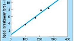
For this test, the time to silt-up completely ranged from one-half to two hours because the tested valves had varying diametral clearances and spool/body-land overlaps due to manufacturing tolerances.
Over the years, a number of technical articles have been published about the effect of silting on sliding-spool hydraulic valves. Most of these articles have not included quantitative data that designers could use to make circuit and component decisions. This discussion tries to take a step forward and provide a basic understanding that will help the designer make system-design decisions which will head off problems before his or her project goes from the drawing board to the hardware stage.
For our purposes, silting can be defined as the build-up of microscopic particles of oil contaminant in the clearance space between a sliding spool and its mating bore in the overlap condition. Degrees of silting can range from a few particles to a massive diametral deposit that completely seals off overlapping land edges of mating spools and bodies.
Variables that affect silting are:
• oil contaminant levels (specifically in the 5-mm or less particle size range)
• pressure differential across the lands
• diameter of the spool
• radial clearance from spool to bore
• number of lands in overlap condition
• length of the overlap, and
• duration of operation.
To discover the magnitude of forces required to break loose a silted spool, we ran some tests using a CETOP 3, 3- position, directional control valve and fluid injected with 5-mm or smaller particles so as to attain an ISO 4406 contamination class of “20” in the 5 mm or less range. The test variable was pressure and the resultants were force to free-up the spool and time to silt-up completely (determined by a complete blockage of leakage around the overlapped lands). In this test, two lands were in the overlapped condition. Test results can be seen in the plot below.
What does all this mean? First, it reveals why most valve manufacturers use the caveat in their catalogs that states: “Valves held under shifted conditions for long periods of time can silt and should be cycled occasionally.” Without adhering to this recommendation, a valve that is expected to shift to provide a certain function may not.
Second, valve selection is an important consideration. A no-spring, detented valve is more likely to fail to shift than a spring-centered or springoffset valve, because all the shifting force must come from the solenoid, and it must overcome not only the detent force but also the silt force.
What can be done if you are stuck — figuratively and literally — with a situation in which it is highly probable that silting will occur? Obviously, the cleaner the oil the better — particularly in the 5 mm or less class. Second, special valves are available for high-silt probability applications. One contains a kicker spool inside the main spool that’s isolated from the system and provides sufficient inertia to the main spool when the solenoid is energized to overcome moderate silting. Another type is a valve which has a standard solenoid on one end and a proportional solenoid on the other. With the proportional solenoid, a system-imperceptible dither can be induced in the spool, which prevents silting from occurring.
The foregoing addresses direct-operated solenoid valves. The problem also can occur on 2-stage valves — either in the pilot or main stage. Hence, caution also should be used when applying these valves.
We hope these comments help you understand at least the magnitude of the forces caused by silting and the time-to silt which may be causing your stuck spool problems — and what can be done to overcome them.
Harry Nowicki
Engineering specialist
Vickers, Inc.
Searcy, Ark.


