Asymmetrical overlap
The ability to set the overlaps at each valve land individually offers an opportunity to gain insight that would not be practical with real valves. Whereas previous simulations have all dealt with perfect symmetry in all the lands, such an idealized condition can never exist in any practical way, due to manufacturing (such as flow grinding) tolerances.
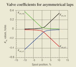
The simulated spool travel has been set to range over ±10% and the number of observations have been reduced from 200 to 100 for a little faster execution and loading, and editing of the graphical results. The key changes are in the four overlaps, which have been set to 1.85, –0.85, 0.85 and 1.05 for KVPL,PA, KVRL,AT, KVPL,PB, and KVRL,BT, respectively. The A-to-T return land has a negative overlap, meaning that it is actually underlapped. This will affect the results, which will be demonstrated.
KVL metering
Asymmetrical under and overlaps are an inevitable consequence of the manufacturing process. In fact, the perfectly symmetrical laps that have already been modeled are only possible in simulation. Figure 1 shows the valve coefficients as a result of input data. The most noticeable feature of the four curves is that the intersection points are not centered, and the two upper curves cross with less shift to the right than the two lower curves do. Therefore, the unbalanced amount of lap results in a null shift.
Asymmetrical lap occurs because of normal manufacturing tolerances when flow grinding. Asymmetry values as great as those given in Figure 1 are debatable. Nonetheless, they can easily be simulated. The issue of zero in a servovalve is itself debatable. In this simulation, the point of zero spool displacement is not ambiguous. It is the exact midpoint of spool travel. That is, simulated spool travel extends from –100% shift to +100% shift, and the zero point is the exact midpoint.
This does not occur in a real valve. Zero is determined only from the measured flow and pressure metering characteristics. At no time do the flow grinding technicians know the spool position nor any of the precise overlaps with any great precision. Instead, the spool metering edges and the body or sleeve ports align (or misalign, as the case may be) in accordance with their actual physical dimensions.
One of the four lands can always be adjusted to zero lap. Which one is zeroed is arbitrary, and the other three have to be flow ground until the desired metering characteristics are achieved. This is done by looking at a set of curves, such as those in Figure 1. Then, through training and experience, the technician decides which lands need to be dressed and by how much. Subsequent testing of the machined spool-sleeve assembly confirms the hydraulic performance of the two parts.
Flow and leakage metering
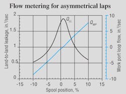
Figure 2 shows flow and leakage metering characteristics of the valve that has asymmetrical laps on the four lands. Again, the curves show the shift to the right, and the spool position for zero crossing is about 1% to the right, but the peak leakage is just slightly more to the right. Most significant in Figure 2, though, is that the flow metering essentially shows critical lap. Only a very slight variation in slope occurs within about ±3% of center. It is important to realize, then, that perfect symmetry is not necessary for good performance. Furthermore, even though one land is slightly underlapped, the peak leakage does not exceed the input value of 2.75 in.3/sec.
Recall that the input leakage value is only an estimate because the actual leakage will be affected by the amounts of the overlaps. The condition of simulated critical lap — like actual flow grinding — is a trial-and-error process. But it is encouraging to know that critical lap can be achieved even with asymmetrical overlaps.
Pressure metering
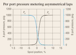
Whereas the metering performance of the valve coefficients, the land-to-land internal leakage, and the flow metering all show nothing that would be alarming to most observers, pressure metering may be a different story. Figure 3 displays per-port pressure metering curves, showing again how they are skewed about 1% to the right due to asymmetrical laps. But more disconcerting is the fact that the intersection of the two curves is well below the ideal crossing of 500 psi (50% of the supply test pressure). In fact, it’s only about 250 psi, about half the ideal value. The cause of the reduced crossing pressure is the underlapped return land A-T. It is more open to tank than its “pressure metering mate” is, (the powered land, P-A). Consequently, there is more pressure across the powered land and less across the return land.
When the valve is finally tested after manufacture, the test technician “nulls the valve.” This means that the null adjusting mechanism, usually a screw, puts a slight bias force on the pilot or main stage such that the condition of equalized pressures coincides with zero current. The amount of null adjustment certainly is affected by the lack of metering land symmetry. The null adjustment is also affected by other factors, the details of which are outside the scope of this discussion.
However, some of those factors are the unbalanced magnetic properties of the pilot, lack of symmetry in flapper-nozzle dimensions, imperfections in the feedback devices between the spool and the pilot, and other electro-hydromechanical effects. When shipped, the valve will have been nulled for equal pressures, which is tantamount to saying that the anticipated application is an equal area cylinder. In the ultimate application, an unequal area cylinder may be used, and the application technician may want to readjust the null for that actuator and its load.
Handbook serves electrohydraulic system designers
The fourth edition of the Designers’ Handbook for Electrohydraulic Servo and Proportional Systems contains even more useful information than its predecessor, the highly successful third edition, which has become the defacto Bible for electrohydraulics technology.
Now you can learn even more about electrohydraulic systems and their design, including:
• how to calculate and control pressure losses in plumbing, subplates, and manifolds,
• how to analyze and control a variety of mechanical loads, including conveyors and belts and triangulated loads,
• valve dynamic properties and how to include them in your system,
• electronics, especially transducers and signal conditioning, and
• mobile equipment electrical systems, including batteries and charging systems.
There is no limit as to how electrohydraulics is going to revolutionize our industry, so order your copy to secure your career in this dynamic technology. And if certification in electrohydraulics is your goal, the fourth edition of the Designers’ Handbook is essential to your preparation. Don’t risk being left behind in a world where the only constant is rapid change.
To order, visit our Bookstore. Print the PDF order form, fill it out, and mail, fax, or e-mail it to us.
