Integral control for electrohydraulic servosystems
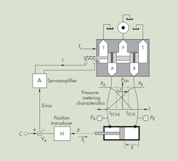
To understand the function of and need for integral control, you must understand the shortcomings and limitations of the proportional electrohydraulic positioning servomechanism. A simplified, combined cutaway and block diagram is shown in Figure 1.
Consider that no load force is on the cylinder, so fL = 0. If the cylinder is to be stopped, the rod-end pressure must exceed the cap-end pressure by the amount appropriate for the cylinder’s area ratio. Furthermore, there must be enough current into the valve’s solenoid coil to sustain holding pressures in the valve.
The holding current is identified in Figure 1 as IST, NL — the stall current under no-load conditions. Applying an external load causes the cap-end pressure to rise, and the metering characteristics of the valve demand that the rod-end pressure drops. The new equilibrium conditions are identified as IST, FL, standing for stall current under full load. Obviously, this requires a change in coil current by an amount indicated by ∆I.
The current results from the servoloop closure, and if the command signal, C, did not change, then the new current could result only from a change in the position transducer output, Vx. The output of the transducer changes only if the cylinder position changes. We conclude then, that the positional servomechanism — under this proportional control — cannot perfectly compensate for load changes, so it inherently produces a load-induced positioning error.
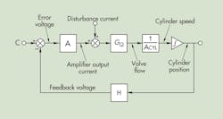
Disturbance forces, fD, which act on the valve spool, yield similar results. All disturbances can be resolved into disturbance currents that act on the valve input. Furthermore, once the loop is designed, and gains have been established, the disturbances can be resolved into output positioning errors. The details will not be revisited here, but Figure 2 summarizes them in schematic form.
The disturbance current can be caused by several conditions, such as supply and tank-pressure changes, variations in load force, and other conditions that affect valve null. Disturbance current is measurable, but the depiction in Figure 2 is somewhat a mathematical abstraction of the actual physical process. It is, nonetheless, useful and accurate enough for explaining the process.
Stopping the cylinder
If we stop the cylinder, it is in a positional steady state, and a necessary force balance acts on the piston. This requires the velocity to be zero. In Figure 2, this means the input to the position integrator must be exactly zero. Similarly, the valve output flow must also be zero; therefore, the effective current into the valve, IEFF, is zero. An equation that summarizes the steady-state condition at the input to the valve flow gain block, GQ, reflects the effective valve current and is given by:
IEFF = ID + C • A – A • H • X
But for positional steady state, the effective input current of the valve is zero, so:
XSS = (ID + C • A)/(A • H)
After separating into two terms:
XSS = ID/(A • H) + (C/H)
This equation is interesting because it shows that in a condition of zero disturbance current, the output position, XSS, is simply the command signal, C, divided by the transducer gain, H, the desired result. But it also describes the effects of disturbance current and clearly shows that the effects of it are reduced inversely proportional to the magnitude A × H. Therefore, even though the disturbances are inevitable, their effects can be held within bounds if the loop gain is high enough.
Indeed, this is a design ploy for systems using proportional control. That is, knowing what load, pressure, and temperature variations to expect, the designer can match the allowable positioning error to the expected disturbance current and determine the gain and closed-loop bandwidth required.
Click here to view the conclusion of this discussion, which is published in the November 2013 issue of Hydraulics & Pneumatics.
Two-for-one offer for H&P readers
The third edition of the Design of Electrohydraulic Systems Industrial Motion Control presents a methodology for the optimal design of electrohydraulic motion control. It contains all the background and root sources for correctly sizing components, designing control systems, closing the control loop, and much more. Anyone interested in, or with a need to design electrohydraulic motion-control systems will find this book a must.


