Open-center valves in mobile equipment - Part 2
Standard schematic drawings provide useful construction details of hydraulic circuits and complete systems, but they do not convey even the slightest insight into proportionality. A more descriptive representation combines a schematic line drawing, such as the two figures from last month, with a cutaway drawing. A valve cutaway shows the spool and valve body parts in realistic relationship to one another, and the schematic line drawing indicates how the multiple sections within a valve stack are interconnected.
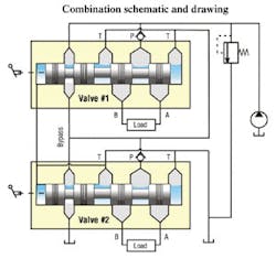
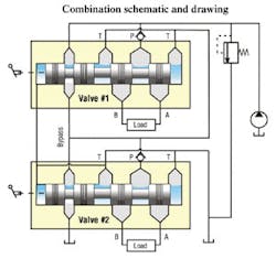
Figure 1 shows a combination diagram of a full series connected stack valve with two directional sections, or functions. This pictorial diagram makes it easy to visualize the effects of partial shift of either or both spools and how shifting the spool results in a partial opening of the valve lands. But, more importantly, it shows how the open-center effect is not achieved by special drilling or machining of the 4-way lands. Rather, it is achieved by including a special set of bypass lands and special bypass paths and interconnections within the valve sections.
Figure 1 also reiterates why some observers object to calling this an open center valve, as in the ISO schematics shown last month. In the 4-way parts of the spools, all ports are blocked in neutral. Is it actually a closed-center valve? In the end, the only things that matter are how the valve performs, what issues confront the system designers, and how the valve stack will interface with the machine operator.
Valve operation
All open-center valves that use the bypass method as depicted here provide a varying flow path as a spool is shifted. That is, when a given spool is centered, fluid flows into the bypass path. If the spool is shifted left or right, the bypass flow path becomes partially restricted, causing supply pressure to rise. Shifting of the spool causes the 4-way spool lands to open, creating an additional flow path from the valve inlet to an outlet work port and from a return work port to the tank port. Further shifting of the spool directs more fluid to and from the work ports and less fluid through the bypass port.
In short, two flow paths are in the valve during partial spool shift — one through the bypass and the other out to the load. The supply pressure is varying (increasing, normally), the bypass flow is decreasing, the load flow is increasing, and the pump output flow remains relatively constant. In this manner, the machine operator is able to control the motion of the output actuator, which is not shown for simplicity. Also, the bypass path serves as the means by which the pump is unloaded with all spools centered.
Checking up on flow
The naming of this interconnection configuration as the full series connection can be seen in all circuit diagrams. It derives from two important facts that apply when more than one function is shifted. First, any flow reaching a downstream function must first pass through all the upstream functions. Thus, we say they are connected in series. Second, the flow that returns from the load recombines upstream of check valves with the bypass flow from the previous function(s).
The check valves are essential to proper operation of the system. Depending on a person’s experience and the valve manufacturer involved, the check valves may be referred to as load-holding check valves, backflow check valves, or transition check valves. I prefer the last one, because it is most descriptive of the actual function.
Figure 1 should be helpful in this explanation. Suppose the check valves were not there, and that one function (say, the second one) has a cylinder that is holding a load, such as the lift axis on a front end loader. If Spool 2 is centered, the load will be held because the work ports are blocked. However, there will be relatively high pressure at one of the work ports, say, work port A. Now, if the operator moves Spool 2 in a direction to further extend the loaded cylinder, when the P-to-A powered land begins to open, the bypass is still fully open or nearly so, and the load-induced pressure will cause the load to descend. In a worst case scenario, the operator will partially open the spool an amount that would cause to load to descend rapidly and dangerously. The transition check valves prevent this from occurring.
The transition check valves are also the cause of the apparent valve overlap. Again, consider the cylinder on the front end loader being partially raised, all spools are in neutral, and the operator wants to raise the load more. There will be load-induced pressure at, say, the A work port that forces the transition check valve into its seat, blocking flow.
When the operator shifts the spool to raise the load farther, the powered lands in the valve open, and the load-induced pressure causes the transition check valve to prevent forward flow. In fact, the transition check valve will not open until the spool has been shifted far enough to close off the bypass path enough to cause the valve inlet pressure to rise above the load-induced pressure. After that, further closure of the bypass path (spool shift) will raise the pressure enough to cause the transition check valve to open. Only then will the loaded load cylinder begin to move.
The net result is that the degree of spool shift needed for output motion depends on the amount of load on the output actuator. This gives the operator the feeling that the overlap of the valve is changing with the amount of load. Some valve designs overcome this apparent valve dead zone. However, that discussion is beyond the scope of this introduction. On the other hand, some machine operators like this effect, because it gives them a better feel for the machine and its load.
Analytical schematic
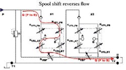
The third type of diagram, the analytical schematic, has been formulated to help in doing quantitative analysis of hydraulic circuits. Quantitative analysis of hydraulic circuits means developing the equations (mathematical models) describing flow and pressure in order to design circuits, size components, run simulations, etc. The analytical schematic for the full series, open-center valve under current discussion is shown in Figures 2 and 3.
Like all schematic diagrams, the analytical schematics ease the writing of equations. However, they fall short in other respects. Unlike previous graphics, they do not depict the logic of spool shifts. In these figures, shifting the spool P to A, causes two lands (in what is now a bridge circuit) — specifically, orifices KVPL,PA and KVRL,BT — to open, while the other two lands, namely, KVPL,PB and KVRL,AT, go further into overlap — that is, shut off.
Figures 2 and 3 show the resulting flow paths for each of the two possible shift directions of section #1. The alternate opening and closing of complementary corners of the 4-way bridge circuits are what facilitate changing the direction of load flows and the variability of the several orifices is what provides proportionality.
The descriptive equations involve summing the flows at each node (circuit junction) and summing the pressures around a circuit loop, just as is done in electrical circuit analysis. Furthermore, it is a relatively simple matter to add hydraulic capacitances at each of the circuit nodes and write the dynamic equations needed for circuit simulations.


