Gain Control of the Flow
This file type includes high resolution graphics and schematics when applicable.
Hydraulic circuits usually have a dedicated power source sized to meet the cycle time, making flow restrictors unnecessary. Flow controls always generate some heat in hydraulic circuits, so consider some other method of controlling actuator speed when possible. The circuit examples presented here explain the types of flow-control systems and how to apply them.
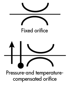
Figure 1 shows symbols for a simple fixed orifice (a rudimentary component that restricts flow) and a fixed orifice with pressure and temperature compensation. A fixed orifice can be a simple restriction in a line or a factory-preset control with pressure compensation and a bypass. Their low cost and tamper-proof operation are two main reasons for using fixed orifices.
Figure 2 shows the symbol for a simple needle valve (top), which is used when fluid flow must be controlled in both directions. The needle valve with a check valve added (bottom) provides pressure compensation in both directions of flow. Pressure compensation only occurs in one direction of flow, so these check valves, sometimes referred to as bridge rectifiers, force fluid through the needle valve in the same direction regardless of actuator movement.
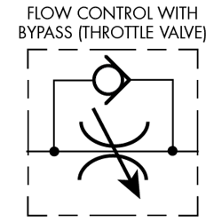
Not surprisingly, nomenclature sometimes confuses this issue in identifying flow-control hardware. Normally, the term flow control refers to an adjustable needle valve with an integral bypass (Fig. 3). This type of flow control meters flow in one direction and allows free flow in the opposite direction. However, some companies identify the valve in Fig. 3 as a throttle valve because it does not provide pressure compensation. The needle valve represented in Fig. 4 does provide pressure- and temperature-compensated flow in one direction.
When a hydraulic actuator needs accurate speed control, use a pressure-compensated flow control. Otherwise, system pressure fluctuations or load changes will affect actuator velocity. Regardless of the cause of the pressure differences, flow across the orifice will change unless the flow control is pressure compensated. However, pressure-compensated valves cost several times that of the non-compensated variety, so use them only when very accurate speed control is needed.
Types of Flow-Control Circuits
Three types of flow control circuits are most common: meter-in, meter-out, and bleed-off (sometimes called bypass). Each circuit has advantages for particular situations.
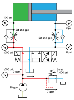
Figure 5 shows a meter-in flow control with the pressures and flows indicated while the cylinder is extending. Notice that a bypass check valve forces fluid through an adjustable orifice just before it enters the cap end of the cylinder. With a meter-in circuit, fluid enters the actuator at a controlled rate. If the actuator has a resistive load, movement will be smooth and steady because hydraulic fluid can be considered incompressible in most cases.
In pneumatic systems, however, cylinder movement may be jerky because of air’s compressibility. As air flows into a cylinder, pressure increases until it generates the force needed to overcome static friction to start moving the load. Because the force needed to keep the load moving is less than the breakaway force (because dynamic friction is less than static), the air in the cylinder actually expands until static friction stops the piston. Pressure builds again to overcome static friction, and the process repeats. This lunging movement can continue to the end of the stroke. A meter-out circuit prevents this stick-slip motion (stiction).
A meter-in flow control will not work if the actuator has an overrunning load (the load pulls on the piston rod). When the directional valve shifts, a strong tensile load on the cylinder rod makes it extend. Because fluid cannot enter the cylinder’s cap end fast enough, a partial vacuum void forms in the line. The cylinder then free falls, regardless of the setting of the meter-in flow adjustment. The pump will continue to supply metered fluid to the cap end of the cylinder and will eventually fill the void. The cylinder can produce full force after the void has been filled.
Meter-out flow controls restrict fluid leaving the cylinder to retard the cylinder’s movement. This type of flow-control circuit works for any type of load—and it works best with air-operated devices.
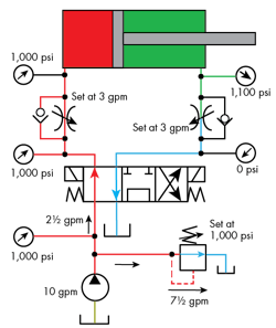
Figure 6 shows a meter-out circuit with the cylinder extending. Fluid in the cap end is at system pressure, and the relief valve dumps excess pump flow to tank. Pressure at the rod end of the cylinder will be at system pressure or higher according to the rod size and force required to move the load. The action of meter-out flow controls is smooth and steady for hydraulic and pneumatic circuits.
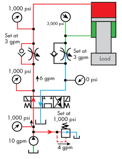
Figure 7 represents a meter-out flow control regulating the load on a down-acting vertical cylinder. This over-running load moves steadily because the circuit restricts flow leaving the cylinder. The meter-out circuit keeps the load from running away but, depending on the load and the rod size, excessive pressure could exist in the cylinder’s rod end. Notice in this case that the rod-end pressure is 3,000 psi when extending. This is because the rod is oversized (2:1) and the load is heavy. At a relief valve setting of 3,000 psi, this rod-end pressure could be as high as 7,000 psi.
A bleed-off flow-control circuit extending a cylinder is represented in Fig. 8. Bleed-off flow controls often are referred to as bypass flow controls. This type of flow control circuit bleeds off excess fluid to tank. A bleed-off flow control works best in hydraulic circuits using fixed-displacement pumps. However, a bleed-off circuit only works with multiple actuators if they operate one at a time.
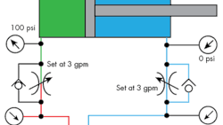
When oil passes to tank through a pressure-compensated flow control, cylinder movement will slow while system pressure rises only high enough to move the load. Although this arrangement wastes energy, the amount is minimal. For example, the cylinder in Fig. 8 extends at 3 gpm while 7 gpm passes to tank through the pressure-compensated needle valve. Because the resistance of the cylinder and load is only 100 psi, the wasted energy is low. In most cases, use a bleed-off circuit where only a small amount of fluid goes to tank in fine-tuning actuator speed.
The 3 gpm flowing to the cylinder generates no heat because it is doing useful work. The 7 gpm going to tank at a 100-psi pressure drop is the only wasted energy—but only 1,038 btu in this case. If the cylinder engaged a load requiring 300 psi, then the whole system would climb to 300 psi. Energy loss would increase but still would be much less than in a meter-in or meter-out circuit.
Even with a pressure-compensated flow control valve, cylinder speed in a bleed-off circuit will decrease slightly as pressure increases. This is because pump flow decreases slightly when pressure increases. The flow control still passes 7 gpm, and when the cylinder bottoms out, pressure increases until the relief valve opens. At that time all input energy generates heat. Note, however, that this only occurs when the cylinder must maintain force while stalled.
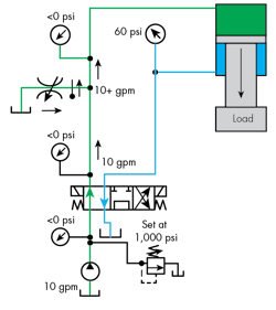
As with meter-in circuits, bleed-off circuits do not work with an over-running load. As Fig. 9 shows, an over-running load can create a partial vacuum (negative pressure) in the pump line. When using a bleed-off circuit with an over-running load, use a counterbalance valve to create resistance.
As with any resistive load, fluid entering the cylinder determines extension and retraction speed. A bleed-off circuit requires a pressure-compensated flow control to keep the cylinder from slowing as pressure increases. Otherwise, cylinder speed will slow down as load increases and speed up when load decreases.
This information was excerpted from “Fluid Power Circuits Explained,” an e-book written by Bud Trinkel and edited by Hydraulics & Pneumatics. Learn more about flow control valves and circuits and many other fluid power fundamentals here.
Looking for parts? Go to SourceESB.
This file type includes high resolution graphics and schematics when applicable.
