A Proposal for Modelling Fluid Power Systems
Download this article as a .PDF
As a young engineering student many years ago, I was taught that an electrical energy source was comprised of an ideal generating element in series with an output impedance. The output impedance accounts for the fact that an internal voltage drop causes the output voltage to fall as load current is increased. It did not occur to me that this was, in reality, a simple mathematical model of a real generator. Only after being exposed to hydraulic circuits and symbols did I realize that they offer no clues as to how the system inefficiencies operate to affect overall system performance. The analytical aspects of the componentry were, at best, only implicit in the symbology. This is clearly inadequate for mathematical modelling of the system.
Component and system modelling is vital when attempting to design or simulate system performance by computer. The computer functions by solving the many equations that explicitly interconnect all the pressures, flows, velocities and forces within and among the various components that make up the system. The ability to mathematically model a hydraulic system remains an arcane technical specialty. Yet, the need to expedite design and convert it quickly—without undue trial-and-error—into real working hardware is vital to the present and future competitiveness of hydraulic machinery. The only way to expedite design is by computer-aided design and simulation, which demands that there be a routine conversion of hydraulic components into useful mathematical models.
Addressing Shortcomings
Electrical engineering component models and simulation software are developed to such a high degree of reliability that it is now commonplace for an electronic engineer to design and debug a new circuit by computer, and then go immediately to a chip foundry to build an integrated circuit without ever building a prototype! There is no hydraulic system modeler I know of who is yet ready to jump from simulation to production—not even the most experienced and most capable among us. However, doing so can be a goal to strive for. There are, in my opinion, several reasons why the state-of-the-art in hydraulic component and system modelling remains in its infancy:
- Too few academic institutions (both in number and in types) express an interest in advancing the art of hydraulic model development and verification. There also remains too little documentation aimed at the specific goals of computerized solutions to hydraulic system problems.
- Divergent viewpoints exist among the few experts in the field regarding just what should be included in a mathematical model. Any two of them likely would not agree on what constitutes a suitable model of, say, a hydraulic pump. I have seen the three equations for position, velocity, and acceleration of a hydraulic motor occupy three pages of closely set type in a recent technical paper on motors. Most practicing engineers use the so-called theoretical torque and flow equations, which are totally devoid of any considerations for internal losses. Somewhere between the two extremes there should be a useful (but manageable) model.
- Our academic institutions that do teach fluid power do not approach it on the basis that the components and systems can readily be modeled. They deal with systems on a qualitative basis, not quantitative. Quantifications tend to be idealized and minimal. Yet, hydraulic systems lend themselves quite well to modelling, and they are very predictable.
- The existing set of component symbols (ISO R-1219) does not assist in the development of analytical descriptions of either the component or the system.
The common practice of giving flow ratings and pressure ratings does not lend itself to model development, nor does it make mathematical descriptions obvious. We cannot ignore such phenomena as leakage resistance and friction resistance. The need for and the units of inductance, capacitance, and resistance in electrical circuits have been agreed upon for decades. This has led to the coefficients needed to describe the componentry in analytical terms.
Not surprisingly, then, powerful computer software for electronic circuit simulation and design has resulted. More important, perhaps, is the existence of universally accepted definitions and methods of evaluation for such coefficients. We do not have an international unit for hydraulic resistance or hydraulic capacitance, nor methods of test. But they could be defined easily, and their values profoundly affect the performance of the hydraulic system. Standardized units might even help the U.S. finally begin metrication.
A Closer Look
For the time being, let’s concentrate on the issue of hydraulic symbols. ISO/TC-131/SC-1 is the international body that deals with the standardization of industrial symbols for fluid power. Its task is to prepare schematic diagrams using symbols that are immediately recognized around the world by those who are skilled in the art, regardless of their native language. This has been accomplished. What is lacking is an agreed-upon means of converting the symbols into quantitative descriptions mathematical models—models that can both explicitly give the viewer a notion of the subtleties of the components symbolized and provide a means of teaching the methods of hydraulic circuit analysis by computer.
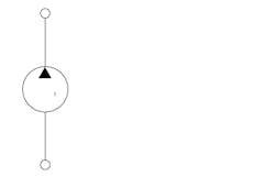
1. The symbol for the ideal pump states explicitly that the pump is 100% efficient.
For this reason, I have introduced a modified set of symbols that assist in the development of mathematical models. I call the resulting circuit diagrams analytical schematics. One of the basic symbols is the conventional positive-displacement pump, but with an “I” within the envelope, as shown in Fig. 1. The I signifies that the pump is characterized in its ideal form, that is, in a form without mechanical or hydraulic loss. The pump is 100% efficient. (This concept of the ideal machine was introduced by Warren Wilson, and further exploited by Jean Thoma and Herb Merritt. The concept has its greatest utility in explaining why a real pump is not ideal. That is, the model of a real pump contains an ideal displacement element plus elements that account for internal leakage.)
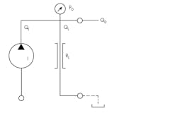
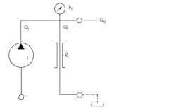
2. A practical pump has an ideal pumping element plus an internal leakage orifice.
A very simple, but very useful, analytical schematic of the output circuit of a pump is shown in Fig. 2. Note that it contains an ideal pump plus an internal leakage orifice to account for actual output flow that diminishes in the presence of increased load pressure.
Several changes should be made to the ISO standard to make modeling easier. The current symbol assortment caters to the practical needs of industry and the physical structures of the components. Symbols of this type do not easily accommodate quantification of the performance. For example, the pump symbol does not allow for identification of internal losses such as leakage and friction that take power away from the power conversion process. A practical pump consists of an ideal energy conversion, plus losses in both the mechanical and hydraulic circuits.
Basic pump technology revolves around the positive-displacement principle. The pump symbol implies positive displacement—that is, a pumping element dependent primarily on the input speed. There is no explicit provision for either hydraulic or mechanical losses, although they clearly exist. If a pump circuit is to be modeled, losses from both mechanical friction and internal leakage must be taken into account. They affect the efficiency and the dynamic performance of the circuits. To ignore them is to idealize them to an impractical extent.
A Simple Symbol
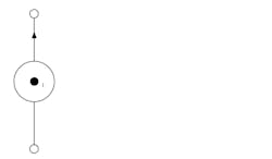
The ideal constant pressure source produces constant pressure regardless of output flow and has no losses.
Sometimes—especially with closed-center valve control—a constant-pressure pump can be simplified without necessarily being idealistic. The practical manifestation of the constant-pressure source is the pressure-compensated pump, many times augmented with an accumulator for dynamic enhancement in the motion-control servosystem. I have often used the non-standard symbol as shown as a simplified notation for a pressure-compensated pump. Other symbol changes would be helpful, but they must be left for another time.


