Post-Compensated Flow Control Made Simple
Terms like post-compensation, flow sharing, and pre-compensation come in handy when exploring predictable flow control in hydraulic systems. When I began learning about oil hydraulics, I had no trouble understanding pre-compensated circuits but really struggled with figuring out post-compensation. For some reason, the concept of flow sharing seemed hard to grasp, and from what I’ve learned, many others find flow sharing difficult to fully understand.
Pressure and Flow Through an Orifice
So, what is post compensation, often referred to as flow sharing? Before we delve into this, some debate whether post compensation and flow sharing are the same thing. Despite opinions to the contrary, I say, yes, they are. One reason many may disagree is because many websites that discuss post-compensation and flow sharing—in my opinion—are written by highly experienced engineers for other highly experienced engineers. They explain the function and benefits of post compensation, but they fail to give a fundamental explanation of the basic principles of flow sharing.
To understand how pressure compensators work, the only thing you must understand is that when oil flows through a metering orifice, the pressure drop (∆P) across the orifice increases with the flow rate and decreases with orifice size. Keeping a constant pressure drop across an orifice keeps the flow rate stable, whether pre-compensation (upstream of the orifice) or post-compensation (downstream of the orifice) is used. The main purpose of any pressure-compensated flow-control system is to keep the flow to an actuator stable by automatically compensating for the changes in load-induced pressure, which achieves accurate and predictable function control.
Starting Simple
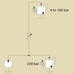
To keep from complicating the discussion, we won’t consider variable-displacement pumps, unloading valves, load sensing, efficiency, overheating, or flow saturation at this point. Instead, we’ll create a basic pressure-source circuit, composed of a fixed-displacement pump working against a relief valve set at, say, 200 bar (3,000 psi). Then we’ll introduce a variable load, represented by another relief valve, and we’ll assume our load can vary from zero to 100 bar (1,500 psi). Finally, we’ll add a variable metering orifice (needle valve) to see what happens (Fig. 1).
1. This model may be oversimplified, but it demonstrates that whenever the load pressure changes, so does the ∆P across the metering element, resulting in speed changes of the actuator.
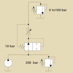
And so, two pilot lines were connected before and after the restriction (to tap into the aforementioned ∆P), and they were applied to both sides of a two-way valve, spring biased in the open position, and mounted upstream the orifice. With this setup, whenever the pressure differential acting on the spool produces more force than the bias spring, the spool tends to close, which throttles the flow and effectively limits the ∆P (and, consecutively, the flow) across the orifice in a self-regulating fashion. This represents a pre-compensated flow control (Fig. 2).
2. Now our circuit is much better; we set the function speed with the needle valve and watch how our flow remains stable and independent from the load-induced pressure.
Understanding the Essentials
It is essential to understand the key feature of this system: the compensator is normally open, and it works (compensates), only after a certain pressure drop (whose threshold is defined by the compensator spring) is reached across the metering orifice. This means that such a system can be regarded as a flow limiter.
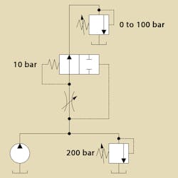
In our scenario, the compensator valve is upstream of the orifice, but you could actually place it downstream, and it would work just the same. In my opinion, moving the compensator downstream does, actually, qualify it as a post-compensated system (albeit not suitable for flow sharing, which is another discussion), but it doesn’t change that it still obeys the same principle. It is still a biased-open flow limiter, in which the compensating pressure drop across the metering element is defined by the spring (Fig. 3).
3. Placing the compensator valve downstream of the orifice causes spring force to determine the compensating pressure drop across the metering element.
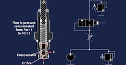
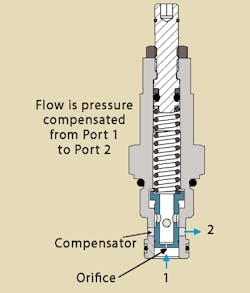
The post-compensated, normally open flow control arrangement is often found in fixed-orifice, cartridge-style flow-control valves because it is the simplest (and least expensive) construction. It consists of a single spring-biased spool with an orifice in it (Fig 4).
4. The post-compensated, normally open flow-control arrangement is often found in fixed-orifice, cartridge-style flow-control valves.
Different Circuit, Similar Result
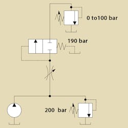
So now we know the orifice needs a constant 10-bar pressure drop to maintain control. However, the pressure at the orifice inlet is 200 bar, so to get a 10-bar ∆P, we need 190 bar at the outlet. All we have to do is fashion a way to induce the 190 bar on the outlet of our orifice to develop the drop we need. We can do this by placing a sequence valve downstream of the orifice, and adjusting it to 190 bar, as shown in Fig. 5.
5. Placing a sequence valve downstream of the orifice and adjusting it to 190 bar produces a 190-bar pressure on the outlet of our orifice.
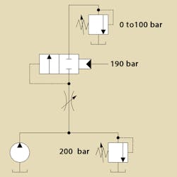
This is a different circuit that delivers a similar result. This arrangement provides the same constant 10-bar pressure drop across the metering element, thus also securing load-independent flow control. Note that this is a sequence valve, and not a relief valve, and even though the valve and load are connected in series, the load-induced pressure does not add to its setting because the spring chamber is vented to tank. In fact, the strong 190 bar spring could be replaced with a 190-bar pilot pressure acting on the spool, as shown in Fig 6.
6. Replacing the strong spring used in Fig 5 with a 190-bar pilot pressure acting on the spool also produces a 190-bar pressure at the outlet of the orifice.
In summary, the pre-compensated system is based on a normally open compensator that works as a flow limiter that senses the pressure drop across the orifice and keeps it below the spring-defined setting. The post-compensated system works as a pressure inducer, ensuring the pressure downstream the metering element doesn’t drop below a certain setting, defined by a supplied pilot pressure (or, as in our simplified example, by a very strong spring).
Grasping this principle (the difference between a flow limiter and a pressure inducer) was an eye-opener for me, and as soon as I started to call these circuits by those names, their function became clear to me. How these compensators behave in systems with multiple actuators under normal and flow saturation conditions is another interesting discussion, which will be covered in a coming installment.
Sergiy Sydorenko is a hydraulics technician and consultant in Rosario, Portugal. This article is adapted from “Post Compensated Flow Control for Dummies,” an entry in his blog, Let’s Talk Hydraulics, which can be found on his website.
