Cartridge valve manifold makes light work of lifting
Railroad cars carry huge loads, typically 250,000 lb. That capacity makes them very economical for long-distance freight transfer. But until the 1950s, moving rail cars very short distances — such as from one track or train to another — was costly and time consuming. The procedure required a conventional switching locomotive, an engineer to operate it, and a switchman to assist.
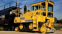
Then, in the late 1940s, Trackmobile Inc., introduced its mobile rail car mover. This vehicle drives around the railyard on rubber tires to the rail car location and positions itself over the tracks. It then lowers a second set of wheels, made of steel, onto the rails. Using a special coupler, it attaches to the rail car and moves it to its new location. The movers’ ability to relocate rail cars more simply and efficiently made them popular workhorses.
Heavy lifting with hydraulics
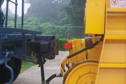
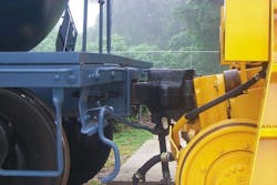
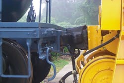
The rail car mover transmits drivetrain power through a torque converter and transfer case. A pressure-compensated hydraulic system operates hydrostatic steering, wheel lifting and lowering, and coupling. However, the coupling procedure is not quite as straightforward as it seems. The rail car mover’s power approaches or equals that of a conventional switching locomotive, but its light weight generates much less traction against the steel rails. To improve traction, the coupler uses hydraulic power to lift the front end of the rail car slightly, transferring some of its weight to the rail car mover.
The lifting action requires care because it is possible to lift the front end of the car completely off its truck. (A simple vertical pin makes the mechanical connection between the rail car body and its truck.) Too little lift produces insufficient traction; too much lift can cause separation. And the rail car may be full, partially loaded, or empty.
Electrohydraulics offers smooth control
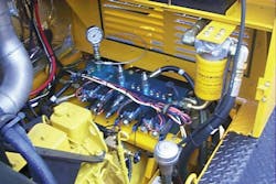
In the 1990s, Trackmobile modernized and streamlined the weight-transfer function on its Magnum line with a combination of rugged microprocessor controls and electrohydraulic valves. The patented Max-Tran autolift system eliminated operator guesswork and ensured appropriate weight transfer and tractive effort. The system consisted of a controller, pressure transducers, control panel switches and indicators, and software, supported by an electrohydraulic cartridge-valve manifold.
The basic concept of the Trackmobile rail car mover hasn’t changed from the Magnum series to the current Titan, Hercules, and Viking Series. The same solenoid operated, hydraulic cartridge valves used on the Magnum series are still in use on the three new series. The integrated circuit is manufactured by Parker Hannifin, but the original valves were not. Because they are so close in design, the newer valves are anodized red instead of the original blue, to distinguish the two. Simply put, the reason for staying with the same valves for so long is that they work so well.
The hydraulic integrated circuit incorporates SV3A-10 solenoid-actuated directional valves and PR3B-10 pressure-reducing/relieving valves, rated for 3600 and 5000 psi, respectively. These cartridge valves are designed and built for low leakage and long life. The directional valves control the cylinders that raise and lower the road wheels and those that position the coupler up, down, left, and right.
A transducer monitors pressure in the coupler’s lifting cylinder, and application-specific software translates that pressure into tractive force. When commanded, the controller adjusts the output pressure of the hydraulic system supplying the coupler. This limits the height to which the rail car can be lifted. The controller’s closed-loop system ensures safe operation. It also adjusts for the weight of the rail car as well as the inevitable variances in track elevations, including dips and hills.
Another aspect of the Max-Tran electronic package — jointly designed by Trackmobile and suppliers — adds anti-lock braking and traction-control functions to the machine. It is now designed and manufactured by Class1, Ocala, Fla. (www.class1.com), according to Trackmobile’s specifications. By monitoring wheel and ground speeds, and comparing them to a predetermined ratio, the control will automatically pulse the brakes and/or the wheel torque to keep the rail car mover travelling smoothly. The versatile package also allows Trackmobile to offer radio remote control as an option.
Simplified functionality streamlines operator control
Several updates to the controls have also improved the MAX-TRAC traction/ABS control system and the MAX-TRAN hydraulic lift system. When the first Titan was designed with the Cummins Tier 3 electronic control engines in 2006, the decision was made to use CAN bus technology throughout the new product line. With goals of increasing operator comfort, safety and performance, we researched many CAN systems and settled on Class 1, which designs and produces custom electronic instrumentation, controls, and plumbing components for heavy duty-ground vehicles.
In the old system, engine and braking systems were controlled with pneumatic foot pedals. The hydraulic coupler lift and traverse cylinders were operated by switches on the console. Pneumatic rail wheel sanding switches were mounted in the corners of the cab, and an air horn was actuated by pulling a chain in the ceiling. In other words, the controls were everywhere!
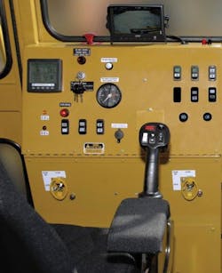
To streamline this, a joystick mounted on the right armrest of an air-cushioned seat now controls the throttle and brakes. The joystick head also contains switches for transmission control, air horn, pneumatic coupler release, and sanding for traction. The left side of the seat has a small control panel that operates the front and rear hydraulic couplers. Also on this panel is a four-position joystick. This electronically controls the rail car’s air brakes. Everything needed to operate the Trackmobile is within easy reach — 22 items are operated from the seat controls and only four wires exit the seat, 12 V positive, negative, plus CAN Hi and CAN Low.
The two CAN wires transmit the commands from the seat module to other modules in the Trackmobile. These modules then send a voltage signal to the hydraulic and pneumatic valves and also the engine throttle. Braking is controlled by wire using a custom module built by Class 1 that controls an electronic MICO brake valve.
The instrument panel was redesigned using a digital display. All the engine, transmission and vehicle parameters are displayed here. This feature greatly simplifies the panel compared to previous models, which had a variety of mechanical gauges.
Bob Evans, engineering manager at Trackmobile, Inc., LaGrange, Ga., can be reached at [email protected] or (706) 884-6651 ext 236. Learn more at www.trackmobile.com.
Hydraulics, pneumatics provide system-wide power and controlPioneering a unique air compressor design Trackmobiles are operated in various environments from very clean (rare) to extremely dirty (the norm), such as paper mills and plastics industries. Wood chips and plastic pellets in these rail yards will eventually plug the radiator of a belt driven fan. The hydraulic fan system on the TIER 4 Trackmobile will, after a period of time, ramp down the speed to 0 rpm and ramp back up in the opposite direction for a short period. This prevents overheating by keeping the radiator from building up debris because the reverse air flow blows debris clear. |
