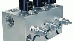
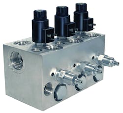
Hydraulic systems a generation ago featured valves that were either threaded for pipe and tube mount, or used a flat gasket interface for sub-plate mounting. These systems were bulky, leaky, heavy, and downright messy. Over the last 20 years, however, many line-mounted components have given way to hydraulic integrated circuits (HICs) using cartridge valves mounted in manifolds. Cartridge valves are installed into a hole on a hydraulic manifold (typically a cube-shaped block of aluminum, steel, or cast iron), which contains internal passages to create all connections between the valves and work ports. Some cartridge valves have threaded bodies that screw into the manifold, while others slip into cavities and are held in place by a cover that is bolted down.
In terms of design, the modular capacity of cartridge valves sets them apart from other valves. For example, a single line-mounted D08 directional valve may be used to control a cylinder, while a hydraulic integrated circuit (HIC) employs four or five cartridge valves for the same job. Thus, each cartridge can be optimized for each of the functional aspects of the large single directional valve, such as asymmetrical cylinder flow, pressure intensification, decompression, soft shifting, etc. By making the cylinder’s cap end cartridges larger than the rod end cartridges (and changing other functions in a likewise manner), cartridge valves circuits can be significantly more energy efficient.
Cartridge valves provide circuit designers with a wide range of controllable flows. Slip-in cartridges offer high efficiency for flows ranging from 80 to 1600 gpm, and screw-in cartridges from 1 to 200 gpm. Therefore, not only do HICs increase power and control density, but they minimize volume and footprint.
Slip into slip-Ins
Slip-in cartridges are usually the best choice in industrial (stationary) systems, particularly when prerequisites include high flows, high pressures, and high duty cycles. Most slip-in cartridges fall into the two-port poppet-valve category, and they are either fully open or fully closed. These are sometimes referred to as logic valves because of their either-or functionality.
All slip-in cartridge valves are pilot operated, meaning that a small amount of pressurized hydraulic fluid is used to shift the valve open or closed. The trick to designing slip-in cartridge circuits is to understand the importance of pilot pressures within the circuit, be able to read and comprehend pilot circuitry, and ensure pilot pressure is always present.
It’s also crucial to understand how orifices control the rates of opening and closing slip-in cartridge valves. Generally, at the circuit-design stage, default orifices that come with covers would be a good place to start. The ability to tune circuits for fast response and low shock by changing the size of control and damping orifices in the covers comes with experience
A slip-in cartridge poppet is normally open, normally closed, and can provide modulated control. Unlike valve spools, poppet valves provide a leak-tight seal when closed. Cartridges that shift from open to closed are directional cartridges, because they either allow flow between ports A to B, or block it. A set of four two-port cartridges can replicate the four-way P-A, P-B, A-T, and B-T functions of a directional valve.
Insert and cover construction
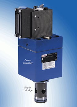
Slip-in cartridges have a two-piece construction: The insert slips into the manifold, and a control cover gets bolted onto the surface over the insert to hold it in place. The cover incorporates all the pilot flows and functions that control the poppet inside the insert and behaves as a main stage for the valve. Different inserts and covers serve different hydraulic functions. When designing a relief (or other type of function), the designer must pick a matching relief insert and relief cover.
Atop the cartridge valve cover is a D03 or D05 interface. It allows for sophisticated control of each poppet underneath via specialized D03 and D05 sandwich valves. Building a sandwich control stack for each cartridge requires caution when applying standard 10-gpm D03 valves as pilot control valves for 0.25- to 0.5-gpm cartridge covers. By adding a proportional pilot valve to the cover, the main-stage poppet turns into an electro-proportional valve.
A drawing of slip-in cartridge valves typically shows the insert and cover as separate symbols. Any sandwich valve symbols can be added on top of the cover.
Thanks to the powerful modularity of slip-in cartridge valves, each sub-function can have a dedicated and optimized cartridge, and pilot functions can be controlled modularly from the main stage. Once again, the slip-in cartridge valves’ two-piece construction makes this possible. One exception is a valve that includes a poppet position sensor. For example, a proportional flow-control poppet cartridge valve typically has one-piece construction and one symbol in a circuit.
A slip-in cartridge fits into a pocket; common pocket sizes are NG16, NG25, NG32, NG40, NG50, and NG63. NG80 and NG100 sizes are less common, and they require extra attention. Although it’s easy to use an NG80 or NG100 valve, manifold manufacturing capabilities tend to be limited for these valve sizes, and lead times on components can be surprisingly long. When drawing up the circuit, it’s helpful to label the port on the insert and the pilot-control ports on the cover.
When selecting a slip-in cartridge valve, understand that a valve’s flow rating is based on flow of a specific fluid at a specific temperature that produces a specific pressure drop. Although valves are typically rated at 5 bar, this does not mean a valve can’t pass higher flow — it will just have a higher ∆P. Still, caution should be exercised when greater flows pass through the valve.
Screw-ins can be shoo-ins
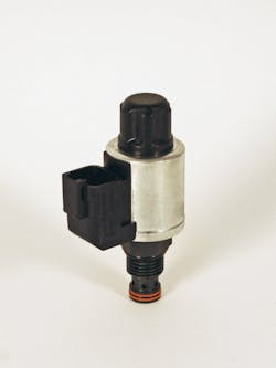
Screw-in cartridge valves screw into threaded cavities and represent a mix between poppet- and spool-type construction. A two-port cavity can accommodate many different types of valves. For example, a C-10-2 cavity can hold a check or relief, or directional cartridge. Other cavities accommodate different valves. Screw-in cartridge valves have single-cage, or one-piece, construction.
Because their capacity starts at very low flows, screw-in cartridges are available as both direct acting and pilot operated. But unlike their slip-in counterparts, pilot-operated screw-in cartridges are self-contained units.
You do not need to match pilot and main stage functions with screw-in cartridge valves. Screw-in cartridge-valves are available in many configurations and with many options, so designers must search through pages and pages of source material to find a specific built-up configuration. After purchase, some screw-in cartridge parts may come in pieces that need to be assembled. For instance, an ac or dc solenoid may ship separately from the valve body.
Two-port screw-in valve cartridges that function like slip-in cartridges are called logic valves. Screw-in cartridges are complete valves for functions, so there’s some duplicity in calling out other valve functions. For example, one manufacturer may identify a specific screw-in cartridge as a counterbalance valve, while another manufacturer refers to it as over-center valve.
Construction of screw-in cartridges often takes the form of multi-port valves. Three-, four-, five-, and six-port valves are common for directional functions. Symbolically, they look like line-mounted spool valves. However, they’re held in a cage that’s screwed into a cavity in a manifold instead of being line mounted. Screw-in cartridges are inexpensive and used extensively in mobile equipment. They have a much smaller footprint than their slip-in cousins, lending themselves to a much more compact manifold. If the valve can handle the flow and pressure, and life expectancy is reasonable, then screw-in cartridge valves become the lowest-cost option. The historical catch, though, has been the cost, time, and risk associated with errors in manifold design, which has drastically changed.
When designing circuits that lend themselves to the screw-in cartridge strengths, line mounted D03, D05 directional and proportional valves often will be used due to pressure ratings, duty cycles, or the unavailability of a screw-in cartridge product or spool type from the vendor. Screw-in cartridges are compelling for lower flows, while multiple slip-in cartridges work better for higher flows.
Key layout considerations
During initial circuit layout, it’s important that ports be identified by the 1, 2, 3, 4 naming convention, which represents the numbering of ports starting from the bottom-most port. This convention ties the hydraulic port on the symbol with the physical port in the hole. It ensures that the manifold designer won’t connect the valve backwards. Most manufacturers have standard common cavity sizes of 8, 10, 12, 16 and 20. A large degree of interchangeability exists between manufacturers (except for Sun Hydraulics, which has a proprietary cavity standard).
A common problem with cartridge circuits is that designers overlook the additive effect of pressure drop across cartridge valves in series. This can be a source of unintentional energy inefficiency.
It’s important to proceed cautiously when specifying flange ports on manifolds for high-pressure and high-flow applications. If a Code 62 flange is called out, it must be clearly communicated to manifold designers, or you could end up with a Code 61 flange.
Care also must be exercised with high-flow SAE O-ring ports. As these ports grow, they get de-rated for pressure. Similar care needs to be exercised by the manifold designer — neither a de-rated SAE construction plug port nor a Code 61 flanged construction port should be used in the manifold when the pressure calls for Code 62.
At the interface between the schematic and manifold design, it’s critical to provide complete component information. It’s not sufficient to either show D03 on the circuit, or even draw a four-way, two-position, spring-offset valve. The ports must be labeled P, T, A, and B, and the model code must be specified. Without this kind of detail, the manifold can be vulnerable to errors or over-designed to compensate for lack of detail.
For example, the manifold designer needs to know whether to leave enough space for an ac coil (which is short), or a dc coil (which is longer). If a spool feedback is used but not shown symbolically, and the model code isn’t called out, chances are good that the manifold will become scrap upon arrival.
When designing an HIC, it’s good practice to provide pressure-measurement ports with each of the work ports. It also helps to identify any other part of the circuit that may need pressure monitoring to set a differential valve for calibration or troubleshooting. A measurement port is especially valuable for a prototype. If the manifold goes into production, the measurement port can be eliminated. A good manifold designer will make a construction hole as a measurement port.
Role of software
When designing HICs, it’s best to use specialized circuit design software. Some manufacturers offer it for free, and other suites are commercially available. Such software ensures a strong tie-in between the symbol, model-code, geometry, cavity, and port numbers and names. In turn, such circuit intelligence is communicated to manifold designers and manifold design software, thus greatly reducing interpretation errors.
After completion of the circuit and creation of a bill of materials (BOM), the manifold is designed either in-house, by a valve OEM, or by an independent manifold manufacturing house that offers design capability. AutoCAD ruled the roost in manifold design until about 2000. But 3D CAD began to emerge in the 1990s, which ultimately led to the widespread adoption of Autodesk Inventor 3D and SolidWorks 3D platforms. Most U.S. manifold designers now use these two platforms that have been equipped with specialized manifold design software. A few valve OEMs use Pro-Engineer and Unigraphics CAD platforms.
These CAD platforms allow vivid visualization of the manifold as it’s being created, resulting in efficient and compact designs. Specialized manifold design software ensures correct connectivity, sufficient clearance between holes, and produces accurate and automated machining instruction.
Migration to HICs
Three macro trends have enabled the rapid growth of HICs. The first is the cartridge valve’s rise from being low-duty-cycle, low-pressure, mobile technology to a more mainstream industrial hydraulic segment. The second trend has been the arrival and widespread adoption of 3D CAD and specialized manifold design software, which has facilitated design. The third has been the adoption of computer numerical control (CNC) machining for manifolds, which has driven down the cost and increased the availability of manifolds.
The upsurge occurring in this sub-segment drives technology and innovation, which further drives growth. This cycle will continue, with the emergence of better cartridge valve and application engineering software tools and the adoption of highly automated, web-based, while-you-wait manifold design software.
Yudhishthira (Yudi) Raina is president and co-founder of VEST Inc. For more information, call (248) 649-9550 or visit www.vestusa.com.


