Cylindrical reservoirs promote cleanliness
The positive effects of having clean fluid in hydraulic systems have been emphasized and generally understood and accepted for more than 25 years. The most important benefits of clean fluid are:
Safety — Clean fluid in a system reduces the probability of failures, which, if catastrophic enough, can actually cause harm to individuals.
Economy — Clean fluid extends the life of components. However, perhaps the greatest economic benefit is gained by a reduction in unplanned downtime, because systems with clean fluid are less likely to exhibit plugged orifices, silted valve spools, and similar sources of malfunctions.
Ecology — Clean oil has a longer life than contaminated oil. This protects the environment and also saves money by reducing the amount of used oil that must be disposed of.
Most of the attention paid to keeping hydraulic systems running clean has focused on initial flushing followed by continuous and off-line filtration. Electrostatic filtering and centrifuge purification have emerged as more intense techniques that remove even the smallest particles, oxidation products, and water from hydraulic fluid. Particulate contamination itself is damaging enough. However, chemical activity between contaminants and the fluid tends to accelerate breakdown of the fluid by producing aging products. Aging products are contaminants that result from the chemical breakdown of fluid due to high temperatures, the presence of water and oxygen, and the deterioration of additives. This is why keeping fluid clean extends the life of fluid— it prevents the condition of the fluid from rapidly deteriorating.
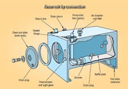
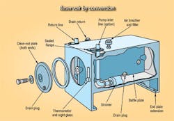
One aspect of maintaining fluid cleanliness has long been relatively ignored: reservoir design. Standardization has helped make hydraulic systems easier to design and certainly more economical, but has caused designers to almost universally specify the conventional rectangular, flat-bottom reservoir, Figure 1. As will be demonstrated, the conventional reservoir not only falls far short of an optimum design, but actually can promote fluid contamination.
Conventional reservoirs and their shortcomings
The reservoir is a basic part of any open hydraulic system and has considerable effect on the daily operation of the system. The roles of the reservoir are to:
• accommodate the variations in the free fluid volume over a working cycle,
• reduce turbulence, so air can escape from fluid and dirt can settle to the bottom of the tank,
• act as a heat sink to help stabilize fluid temperature, and
• serve as a mounting surface for pump, motor, valves, accessories, and other components.
The usual configuration that meets these requirements is a rectangular container with flat sides, ends, top, bottom and at least eight corners, Figure 1. Inside is a baffle, screen, or both to slow down the flow of fluid from its entry into the reservoir until it reaches the pump suction line inlet.
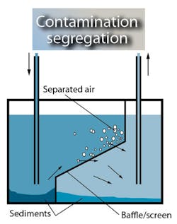
The rectangular reservoir, for the most part, meets the requirements outlined above, provided that sediments are removed regularly from the reservoir floor and that the inside of the reservoir is cleaned periodically. However, the many components inside the reservoir and its many corners make it difficult to be cleaned thoroughly. Consequently, technicians may ignore regular cleaning schedules and attempt cleanup only when absolutely necessary. Unfortunately, a condition similar to that shown in Figure 2 often results — thick layers of sediment covering the bottom of the reservoir.
Realizing the severe negative effect on fluid cleanliness from the long term influence of settled contamination — combined with the low priority given to cleaning out the reservoir — perhaps some of the roles of the reservoir should be altered. For example, letting contaminants settle onto the bottom of the reservoir keeps them in continuous contact with the fluid, thereby affecting its chemistry. Moreover, the surface of this sediment layer is very unstable, so a change in the return oil flow rate or direction can stir up clouds of contamination in the otherwise clean fluid. Even with careful flow regulation, stirring up this sediment layer cannot be avoided in mobile and marine applications.
A new strategy
Contaminants, therefore, should not be allowed to settle in the reservoir; they should be removed as soon as possible through filters and water coalescers. The most effective way to do this is to adopt a reservoir shape different from the traditional “bath tub” that has become so prevalent. This shape has already been in use for decades in aviation applications, where any disturbance in the operation of a hydraulic system could prove catastrophic.
One self-cleaning reservoir is presented in Figure 3. The reservoir takes the form of a vertical cylinder with a conical bottom. A smooth transition joint exists where the vertical side wall meets the conical bottom. The suction connection for a filter or filtration circuit is located in the lowermost part of the reservoir, at the apex of the inverted cone. The return flow inlet is tangential to the cylindrical wall. When the return flow enters the reservoir, the entire mass of oil tends to slowly rotate.
Rotating the mass of fluid directs contaminants toward the center of the reservoir. This action can simply be demonstrated by stirring a cup of tea. Fluid dynamics divert the tea leaves into the vortex of the spinning fluid. The same principles govern the rotating hydraulic fluid: solid contaminants concentrate at the center of rotation. This principle differs from that in a centrifuge, where rapid spinning introduces centrifugal force many times that of gravity, which directs particles away from the center of rotation. Unlike fluid in a centrifuge, fluid in the reservoir rotates relatively slowly, so fluid dynamics have a much greater effect on particles than centrifugal force does. Because the solids are more dense than the hydraulic oil, they eventually settle to the bottom center of the reservoir, where the filtration circuit inlet is located. From there, contaminants will be trapped by the filter instead of collecting at the bottom of a flat surface.
It is essential to rotate the mass of oil under normal operating conditions to keep particles, water, and other foreign contaminants from settling. In this manner, contamination is kept suspended in the oil until it is caught in a filter. Most of the contamination is taken out of circulation the first time it encounters a filter. Furthermore, filters are much easier to maintain than reservoirs are. Replacing a dirty filter element has become easier and more convenient than ever, and indicators make it easy to determine when an element needs to be changed. Cleaning reservoirs, on the other hand, is an unpleasant, labor-intensive procedure. Moreover, it is difficult to determine how dirty a conventional reservoir is without emptying and inspecting it. By the time you go through all the trouble, you should probably clean it anyway.
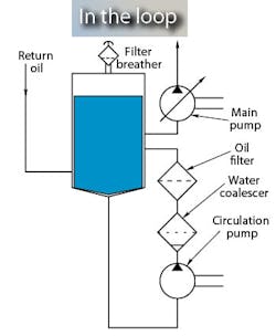
A bypass filtration circuit, sometimes called a kidney loop, works especially well with the cylindrical reservoir. A kidney loop often incorporates an oil cooler or heater as well. Fluid from the kidney loop flows back to the reservoir through a tangentially oriented tube, Figure 4. The main system pump draws fluid from the upper portion of the reservoir, where fluid is cleanest. Return oil flows tangentially into the reservoir near the bottom. No unwanted substances will be accumulated any place in the system because particles and other contaminants are continuously removed. At no time are they given an opportunity to accumulate anywhere. This results in simpler maintenance procedures, longer fluid life, and higher system reliability.
Better by design
A secondary benefit of vertically oriented cylindrical reservoirs is better utilization of the materials than with conventional designs — especially when larger reservoirs are required. When the reservoir must exceed approximately one meter in height, hydrostatic pressure of the liquid column has to be considered to prevent the reservoir’s side plates from deflecting outward. To reduce or prevent bulging and strain in the material, designers often specify corrugated side plates or heavy gauge steel for constructing the reservoir, or they specify ribs for added stiffness. Welded ribs, however, are expensive to install. Furthermore, locating them inside the reservoir creates corners and crevices that collect contamination. However, locating them outside the reservoir is a losing proposition too, because they consume additional floor space.
In a cylindrical reservoir, the hydrostatic pressure itself presents no practical impact on the thickness of the side plate. This is because the geometry of a cylinder distributes stress from the hydrostatic pressure evenly around the circumference of the reservoir. The construction need only be strong and stiff enough to allow transporting the empty tank, which serves as a base for its flanges and connections and carries the weight of the fluid.
In comparing two reservoirs with identical volumes, a cubic reservoir with top, bottom, and sides 2-m square has a volume of 16 m3 . A cylindrical reservoir with the same height and volume would have a diameter of about 2.55 m. With the cubic reservoir, side plates would have to be 14 mm thick to withstand the hydrostatic pressure from a column of oil, and bulging would be approximately 15 mm. On the other hand, plate thickness for the cylindrical reservoir would only have to be 0.25 mm or less. Furthermore, diametral deformation from hydrostatic pressure would be only about 1 mm.
What this all boils down to is that cylindrical reservoirs not only promote cleaner fluid, but can be less expensive and lighter weight due to simpler design and more conservative material requirements.
Bård A. Harang is owner of Hymatic AS, Trondheim, Norway. For more information, contact him at [email protected], or contact Hans Martin, project engineer, PMC Servi Group, at [email protected].
About the Author

Leaders relevant to this article:


