In motion control, it is often desirable — or necessary — to stop a moving load smoothly. A rubber bumper, a compression spring, or a dashpot all can accomplish this by absorbing energy. The bumper and spring store energy and release it after they are compressed, resulting in a rebound. A dashpot is a fluid-filled cylinder with an opening through which fluid may escape at a controlled flow. Any force acting against the piston in the cylinder encounters high resistance from the fluid at the beginning of the stroke, then much less as the piston retracts. However, none of these three items dissipate the energy uniformly. The impact of a moving load against a resisting force produces peak forces, which are transmitted to the machine’s moving elements or to the load itself. In order to dissipate the energy uniformly, the use of a shock absorber is required.
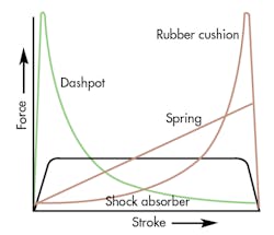
The graphic shows plots of force versus stroke for the same load moving at the same velocity striking a rubber bumper, a spring, a dashpot, and a shock absorber. The kinetic energy to be absorbed is the same in each case, but it is dissipated at differing rates. A linear rate of deceleration is the most efficient combination of force, space, and time that can be used to stop a moving object. The ideal rate is an almost square curve, where a constant force resists the load, until it is slowed to a stop.
Shock absorbers decelerate loads linearly
Shock absorbers convert the kinetic energy of a load into heat that is dissipated into the atmosphere. They stop a moving load with no rebound and without transmitting potentially damaging shocks to equipment.
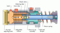
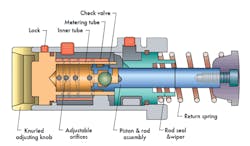
In its most general form, a shock absorber consists of a double-walled cylinder with space between the concentric inner and outer walls, a piston, some means of mechanical return for the piston, and a mounting plate. The piston return is usually a spring, which can be mounted externally around the piston rod or internally on the inside of the cylinder body. A series of orifices are drilled in the inner cylinder wall at exponential intervals. The reason for the exponential spacing is derived from the equation for kinetic energy: KE=1/2 mv2.
The cylinder is filled with fluid; all air is bled from the fluid because air bubbles cut the efficiency of the shock absorbers by causing spongy or erratic action. When a moving load contacts the piston rod, it moves the piston inward, forcing fluid through the orifices in the inner cylinder wall. The fluid is forced through the oil return passages, into the space behind the piston head. As the piston retracts, it closes the orifices behind it, reducing the effective metering area, and maintaining a uniform deceleration force as the load loses its energy.
Fluid pressure is constant in a shock absorber, providing constant resistance to the load. The load slows to a stop as its kinetic energy approaches zero. There is no rebound because the shock absorber stores no energy. To return to its extended position, several events must happen. First, the load must be removed from the piston. The spring then pushes the piston outward, opening a check valve, which permits fluid to flow from behind the piston to the space the piston was in when retracted.
Smaller shock absorbers, with bores under 3 in., have a ball check valve to control fluid flow. Larger models use a piston-ring check valve.
Fixed vs. adjustable shocks
There are two basic types of shock absorbers: those with a fixed orifice, and those with an adjustable orifice. The fixed type, sometimes referred to as non-adjustable, has orifices drilled along the inner cylinder wall at distances determined by the manufacturer. While generally less expensive, they are designed for a specific application’s load range and cannot be changed to meet the requirements of other applications. They are more economical in high volume applications where the exact operating parameters will not change significantly over time.
Adjustable-orifice shock absorbers can accommodate a range of loads - as much as 30 times the range of a non-adjustable type. They are adjusted by moving a graduated dial on the outside of the shock absorber. This moves a ring around the orifices to control the size of the openings.
Controlling the amount of fluid forced through the orifices controls the deceleration rate. The dial rotates through 90° or 180°, and is calibrated on a scale from 1 to 10. Usually, the higher the number, the greater the resistance to impact. Generally, adjustments are made by observing energy absorption at different settings. Constant resistance to the load should be evident throughout the stroke of the shock absorber.
Orifice design
Orifice design is critical to the operation of a shock absorber. A circular hole drilled in the inner cylinder wall will permit fluid to flow to the outer portion of the cylinder, but causes pressure drop or a change in fluid viscosity due to change in fluid temperature. A simple hole will produce laminar fluid flow, which is less efficient in dissipating energy and often cannot be controlled precisely.
As a shock absorber cycles more and more frequently, and if there is a high amount of laminar flow through the orifice, the operating temperature will increase. The resulting change in fluid viscosity will require constant readjustment of the shock absorber. A knife-edge orifice is very short when compared to the thickness of the inner cylinder wall. These produce non-laminar flow, which is not sensitive to changes in fluid viscosity, and is easily controlled.
Selecting a shock absorber
When choosing a shock absorber, the most important factor to consider is the type of load to be stopped. Basic loads encountered in shock absorber applications include: pure inertial, free-falling, rotating, and loads subject to an additional propelling force. Load weight and velocity are the next two most important factors in sizing a shock absorber. Potential shock to equipment, number of impacts per unit of time, and ambient conditions must also be considered to properly select a shock absorber.
Application conditions include extreme temperatures, load acceleration, maximum propelling force applied to the load, and time limitations imposed on the equipment. Time limitations would include minimum and maximum cycle times and the time required for the shock absorber to return to the extended position between strokes. Cycle rate is another important consideration. If the shock absorber must handle too many impacts within a given time, it will overheat, resulting in poor performance and premature failure. Rapid cycling may heat the fluid, reducing its ability to dissipate energy.
As a safety feature, most manufacturers recommend that shock absorbers be sized for 70% to 80% of capacity. Because the amount of impact the shock absorber can accommodate is inversely proportional to the length of its stroke; doubling stroke length will cut the impact of the load in half.
Mounting
Shock absorbers must be bolted rigidly to a non-flexing mounting structure. Some type of external stop is required to provide a firm positioning point, and to prevent the shock absorber piston from bottoming out at the end of its deceleration stroke. Mounting can be achieved through a drilled hole and secured by a mounting stop collar, rear mounted into a drilled and tapped blind hole and secured by a jam nut, or via its own mounting flange.
Applications
Shock absorbers can be used in a myriad of places. Applications include straight-line functions, as well as rotary, free-falling, rolling, and sliding movements. It makes no difference if the action is driven mechanically, hydraulically, or pneumatically. One common situation for shock absorbers is on high-cycle automation machinery that use rotary motions. For this the shock absorbers should be positioned near the pivot point to provide more clearance for the work area. However, this placement subjects the shock absorbers to high effective weight conditions due to their low velocity. Most of the kinetic energy involved originates from the propelling force rather than from inertia. For such applications, specify shock absorbers designed to operate in a velocity range from 1/4 to 2 ft/sec.


