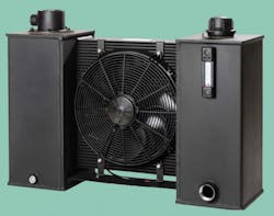
Extra fluid and cooling for compact hydraulic systems
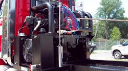
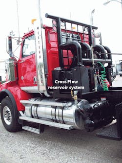
As space becomes more limited for hydraulic power units in mobile applications — such as this oil-field truck — heat dissipation becomes a greater challenge. One solution, Parker’s Cross Flow reservoir system, provides additional cooling in a compact, lightweight package.
Higher power densities and shrinking dimensions dominate today’s hydraulic system designs, making thermal performance all the more critical. In many systems, the reservoir is the only heat sink that provides cooling. It’s thus become impractical to sustain the rule-of-thumb volume equal to 2½ to 3 times the pump flow, which allows for this heat exchange. Now designers are investigating new limits to optimize systems while maintaining thermal performance.
It’s difficult to understate the importance of operating at the proper temperature. For example, the sensitivity of oil viscosity to temperature influences lubrication and leakages. A 20°C rise in temperature can reduce the viscosity by one-half, which compromises the immediate performance and longevity of the system’s components.
Temperature vs pressure model
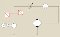
A model based on the conservation of mass and energy better illustrates how hydraulic systems respond to changes in temperature and pressure, Figure 1. The primary heat sink is the reservoir or cooler and the main source is the loading valve, which are described in Equations 1 and 2, respectively.
(1) dT/dt = ( m × Cp × ∆T – q) / (M × Cp)
(2) dT/dt =[ Qth × ∆P+(m × Cp × ∆T)] / (M × Cp)
where
T = temperature
t = time
m = mass flow rate
Cp = specific heat capacity
q = rate of heat transfer
M = control mass
Qth = Flow (adjusted for thermal expansion)
P = pressure.
Equation 1 defines the pressure drop across the reservoir as negligible, and simplifies to the heat stored minus the heat lost to the environment. Equation 2 considers the pressure drop across the valve, the heat stored, and the heat lost to the environment (for simplicity, the second and third terms are neglected). Other potential sources include the pump and piping, which can be described similarly to the pump and reservoir, but they also are neglected for this purpose.
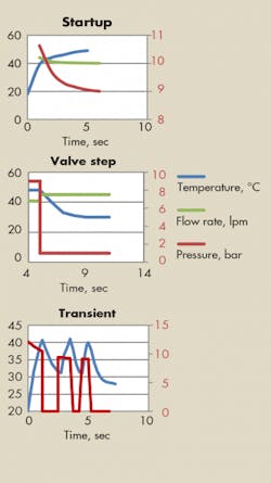
Using the model in Figure 1 above, rising oil temperature leads to decreases in pressure and oil viscosity during the warm-up phase (Figure 2, top). In another case with the model, a discrete shift in the flow-control valve causes the characteristic lagging response of temperature (Figure 2, middle). Repeated shifting of the valve presents another scenario of the temperature’s effect on pressure (Figure 2, bottom). The two key points illustrated with these graphs are that system temperature can’t ever reach equilibrium and peak load isn’t maintained.
When evaluating the “2½ to 3 times the pump flow for volume” rule of thumb, the primary concern becomes the rate of heat transfer, q, which is a function of the environmental condition and very difficult to precisely predict. By viewing the heat and calculating the overall heat transfer coefficient, U, as shown in Figure 2, you can assume that the internal wall temperature is the same as the that of the oil. This means RC = 0 in Figure 3.
(3) U = 1 ÷ [Σ(Li/ki) + Σ(1/hj)]
= 1 ÷ (A • Rth)
L = length
k = thermal conductivity
h = film coefficient
A = area
Rth = thermal resistance
(4) Q = U •A •∆T
where:U = overall coefficient of heat transfer.
A further assumption of 12-gauge steel results in RB being negligible. This simplifies Equation 3 so that only the external film coefficient, h, is considered. The result is that U ends up in the 30- to 40-W/m2k range.
Overall heat transfer coefficient has a large range. Consequently, machine designers often push the higher values by designing a reservoir that maximizes surface area, is in the path of air flow, and is away from heat sources. Interestingly, while the change of reservoir material from steel to aluminum drastically reduces RB, the change isn’t significant enough to achieve the desired thermal performance.
Perhaps a cooler?
With the aforementioned considerations to reduce thermal resistance, designers have successfully pushed the flow:volume ratio down to one. A cooler may be required when the ratio drops any lower, say in extreme environments that minimize the differential temperature, or mounting provisions that reduce the heat transfer coefficient. This also may occur with heavy duty cycle systems.
A cooler’s size often is based on approximate system efficiency at full power, where constant pump systems have an estimated efficiency of 70 to 75% and variable pump systems come in at 75% to 80%. Another means of sizing involves breaking the system down into its components by the anticipated volumetric efficiency of the rotary components and the anticipated pressure lost across controls at full system load. A more accurate means of estimating the heat load would break down the cycle by peak loads, and then use a time-weighted average to obtain the average heat load that determines the cooler’s size.
The worst-case scenario may be accounted for on the environment side, assuming the lowest temperature differential or film coefficient. Often, the worst case is considered several times during design by assuming steady-state max load, extreme environments (low ΔT), and poor performance of components (low h). This has a multiplying effect on the cooler size, which results in excess heat exchange capacity, size, and weight.
Proprietary heat exchanger designs, such as Parker's Cross Flow Reservoir System, can further reduce footprint and weight. These units integrate multiple components into one assembly, which minimizes the number of connections needed and provides a compact assembly. The challenge here is the limited flexibility to configure a system.
Systems like heavy-duty-cycle closed circuits demand such flexibility — full flow is required through a cooler, while only a portion is held in reserve. Another example involves any system with a large exchange capacity. However, when recognizing these limitations, these units prove convenient for maintaining thermal performance in demanding applications. Moreover, their capabilities continue to expand to fit the market.
As designers push hydraulic systems to their limits, it’s important to understand the thermal response, the effects on a system, and how to design for thermal performance. Old rules are becoming outdated due to more precise, new designs. Fully modeling the thermal response may not always be practical, but understanding the trend and being able to anticipate loading will help pinpoint optimal products. It will ultimately lead to easier assembly, better performance, and lower footprint systems that meet market demands.
As designers push hydraulic systems to their limits, it is important to understand the thermal response, the effects on a system, and how to design for thermal performance. Old rules are becoming outdated as new designs become more precise. Fully modeling the thermal response may not always be practical but understanding the trend and being able to anticipate loading will help to choose products that are optimal. This understanding and expanded product offering allows for easier assembly, better performance, and lower footprint systems that will serve the markets needs.
John Trott is Design Engineer with Parker Hannifin’s Hydraulic Filter Div., Metamora, Ohio.
To request a PDF file describing Parker’s Cross Flow Reservoir System, e-mail [email protected] and request brochure #SS-0008.
This article appeared in print as "Beat the Heat in Compact Systems" in the September 2013 issue of Hydraulics & Pneumatics.
