Hydraulic-Electric Analogies: Reservoirs and Grounds
The term ground may cause confusion because of the way it’s used, especially in electronic control systems. Let’s first clarify what ground is and what it is not. The term derives from the fact that the electrical power industry uses earth as a conductor. This reality erroneously leads many people to believe that earth “sucks up” all the excess current by some perceived magic. Coupling that with TV pictures, typically from drama-seeking reporters, of hurricane-downed power lines dancing and arcing in the storm only reinforces and perpetuates the myth.
This file type includes high resolution graphics and schematics when applicable.
There’s a reason why this occurs, and it’s not because earth has some mystical power. Instead, earth is just another conductor that can complete electrical circuits. The downed wire is the “high side” or “hot side” of the power transmission line. Arcing occurs when the downed high-side wire makes contact with the earth, and will cease only when someone shuts down the upstream power substation or until the current exceeds the capacity of the upstream circuits.
If you’ve been involved in the wiring of your house, for example, you become aware of the electrical codes that require one side of the house wiring (the green wire) be connected to earth. This is a hard and fast safety rule. Tracing back that wire will lead you to a stake driven into earth, or a physical connection to a water pipe that’s buried underground. So now, the low-side wiring (ground) of every house, factory, and any other building is connected to the power company through the earth. Meanwhile, a common connection links everything to the power company, just as intended.
With the advent of practical electronics and its burgeoning technological advances, the term “ground” has become corrupted in the jargon. It’s evolved into “any common point in a circuit to which all circuits return,” which doesn’t necessarily mean that it’s earth. Unfortunately, the term ground has replaced the more useful and descriptive circuit common or simply common that’s preferred by this author. There will be more on this issue later.
Symbology
Electrical ground is almost perfectly analogous to the reservoir in a hydraulic system. Even the symbols and their uses are similar. The terms reservoir and tank are used synonymously — some hydraulic circuit schematics will label the outlet port with T and others may use R, but they both carry the same meaning and interpretation. The former means, literally, tank, and the latter can be defined as either return or reservoir.
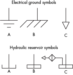
Figure 1 shows the most common symbol forms for electrical ground and electrical common, along with conventional symbols for hydraulic reservoirs. The electrical symbols are circuit common — (A) a point in the circuit to which all currents return; (B) earth — used by the power company as well as for all power wiring, and to which all power currents can return (in the event of a ground wire fault or break); and (C) an alternative form of the circuit common (an open arrowhead) that has found broad acceptance, in large part, because it takes fewer moves to draw in modern drafting software. So now, the open arrow, c, means an alternate ground or common point in electrical circuits, but atmospheric venting in the hydraulics world.
Three conventional and common forms of the hydraulic reservoir symbols are also provided in Figure 1. The first is the most commonly used symbol because it represents the most common form of the hydraulic reservoir installation (A). It depicts a reservoir that is open to the atmosphere, which may or may not be vented through a filtering air port. The symbol, in its simplicity, is silent on that issue.
The second variation (B) represents a sealed reservoir that could be pressurized, but there’s no assurance that the internal pressure will be atmospheric without further information, which most assuredly be provided by the first type. An external, regulated pneumatic supply pressurizes some sealed reservoirs, while others come equipped with bladders or other pneumatic barriers to prevent excessive air dissolution in the hydraulic fluid.
The third symbol (C) is a sealed reservoir that’s vented to atmosphere through a filter. From the standpoint of pressure, the first and third types essentially perform in an identical manner. It’s true, however, that the hydraulic reservoir level rises and falls with the extension and retraction of single rod end cylinders.
As the liquid level changes, ambient air is alternately ingested and exhausted. With air ingestion, unwelcome ambient contaminants will make their way into the reservoir, potentially causing serious damage to the precision hydromechanical parts. The filter is a safeguard against such damage. The open arrow in reservoir symbol (C) indicates venting to atmosphere.
Ground-Reservoir Parallels
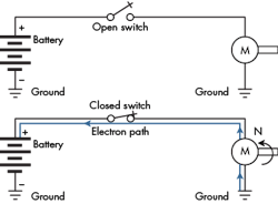
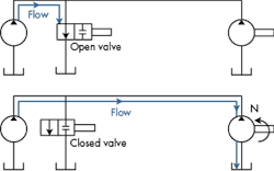
Ground and reservoir are analogous concepts. In Figures 2 and 3, placement of the ground (circuit common) in the electrical circuit is similar to the reservoir’s connection in the hydraulic circuit.
We could define the reservoir as the point in the circuit where all flow must originate and eventually return. However, the electronic circuit designer has more flexibility in defining ground placement than the hydraulic system designer has in defining the reservoir’s logical placement in the circuit (not to be confused with physical placement in the room or vehicle).
Rules for drawing schematics, according to established standards as well as common practice, are the same for circuit grounds/commons and hydraulic reservoirs. The circuit in Figure 2, for example, uses two distinct ground symbols, but it’s conventionally understood that the two are actually one and the same. In fact, it’s possible that in the physical circuit, both grounds represent connections at the same physical point.
So, too, is the case with hydraulic reservoirs. Again, convention dictates that without information to the contrary, all individual reservoir symbols represent one—and only one—physical reservoir. The reason for both electrical-ground and hydraulic-reservoir conventions is that it disencumbers and de-clutters the drawings from needless lines.
Remember, though, that electrical circuits can incorporate multiple grounds in a single system. Such multi-ground circuits result from the natural ground isolation property of transformers. With hydraulic systems, it’s a different situation. Special, total isolation methods are necessary to accommodate multiple physical reservoirs lest all of the fluid end up in one reservoir, thus starving one of the circuits of hydraulic fluid.
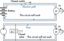
Looking at Figure 4, you’ll see that the electrical circuit has no ground, and yet it will function perfectly well. In this case, the circuit is said to have “a floating ground,” or “floating common,” even though there’s no ground per se. Note that the reservoir, in analogous fashion, was removed from the hydraulic circuit.
Anyone with hydraulic experience will realize that the hydraulic circuit is highly susceptible to cavitation, because there’s no means for keeping the lowest pressure (pump inlet/motor return line) above that which will result in cavitation. The reservoir, as shown in Figure 3, allows the motor outflow to occur at ambient pressure, and the pump inlet is aided by atmospheric pressure as it fills.
Unlike the hydraulic circuit of Figure 4, the electrical circuit isn’t encumbered by cavitation. In fact, an electrical circuit will never experience cavitation. The electric motor can “suck” as many of those electrical charges as it needs and at whatever negative voltage it needs, no matter where those little charges may be ensconced. Voltages can go as far negative as is necessary to satisfy the physical laws of electricity. There’s no such thing as absolute zero voltage anywhere in the universe.
A real place of absolute zero pressure does exist, though. It’s called a perfect vacuum. Never mind that it can’t be achieved in the strictest sense. We can imagine a place so devoid of molecular activity (gas) that it could be considered a perfect vacuum. In a hydraulic circuit, if the pressure is reduced but remains a small amount below atmospheric, dissolved gasses come out of the solution in a process called “out-gassing,” which often leads to cavitation damage.
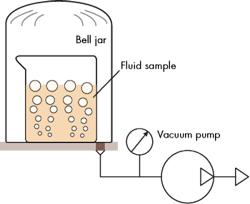
Regarding out-gassing (Fig. 5), some people say that the extraction of dissolved gases (mostly air in hydraulic systems) from liquids under reduced pressure results from the liquid “boiling” due to reduced pressure. Indeed, liquids will boil at lower temperatures when the ambient pressure is reduced. But out-gassing occurs at temperatures substantially below the fluid’s boiling point. Furthermore, the out-gassing stops when enough of the gases have been extracted at the new, lower pressure. Boiling will continue to spew forth gases as long as there’s a heat source (temperature) and liquid.
A simple experiment proves this point: Place a sample of hydraulic fluid (oil) that’s been resting in normal atmospheric conditions inside a sealed, transparent bell jar connected to a vacuum pump. When the vacuum pump is started, and the vacuum reaches about 1/3 of an atmosphere, bubbles begin forming as dissolved gases are “released” from the fluid. Stopping the vacuum level and maintaining the vacuum will eventually stop the bubbling, because the fluid’s vapor pressure will have reached ambient pressure inside the bell jar. If the fluid were literally boiling, the bubbling would continue. This is the same process that causes carbon-dioxide bubbles to form after opening a carbonated beverage.
Points of Placement
There’s little controversy over where to place the reservoir in the hydraulic circuit. It has to be at the pump inlet, and the motor return line sends its fluid back to the reservoir. Thus, the pump inlet line and motor return line are common through the reservoir.
Ground location is different. The circuit ground can be placed anywhere, with only a few well-defined exceptions.
For example, the circuit in Figure 6 has three different ground points. Each one represents an optional choice for ground location, but only one location can be chosen. The important point here is that the actual location makes absolutely no difference. Ground can be placed at any one of the three optional points, or ground can be eschewed altogether, and the circuit will function just fine.
That choice doesn’t exist when placing a reservoir in hydraulic circuits, because the absolute pressure is limited in terms of how low it can go to reach the lowest absolute pressure in the system. The tank and its atmospheric pressure serve to provide a degree of control regarding the minimum absolute pressure. As mentioned, there’s no absolute zero voltage point in electronics. In fact, such a concept is nonsensical.
There’s a common misconception that ground (earth) somehow will suck up any electricity thrown at it. It’s simply not the case. Rather, it’s merely one conductor in the electrical power grid, because many years ago, the power industry chose to connect one side of its alternators to earth.
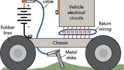
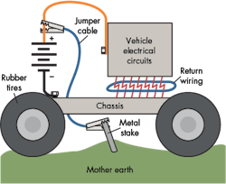
I often ask my students, "What would happen if you took a metal stake, drove it into the ground about two or three feet, and then connected a jumper cable from your car battery's positive terminal to the stake?" The answer is “nothing,” as can be seen in a simplified schematic of the automobile and its electrical system (Fig. 7).
The reason is that no complete loop is formed between the positive battery terminal, through the blue jumper cable, through the stake, and then through earth — which is the end of the circuit. The electrical circuit is open. The tires, being electrical insulators, prevent any current from flowing through the jumper cable and earth. If you decide to try this experiment, make sure it's done with a car with tires. If it's sitting on rims, there could be a complete current loop, i.e., a closed circuit loop.
While we’re on the subject of automotive electrical systems, SAE J1908 (a standard for vehicle grounding) allows for three different ground points in a vehicle. They are distinguished, one from the other, by the amount of current that each is allowed to carry. Ideally, there would be only one ground, requiring all return connections to be terminated at the negative terminal of the battery. Its impracticality becomes immediately apparent, so the vehicle’s body parts serve as the common return, i.e., vehicle ground.
The bundle of connections in Figure 7 labeled “Return wiring” suggests at least two different grounding points, one being inside the box labeled “Vehicle electrical circuits” and the other being the chassis. The one heavy
black return cable would likely be for the starter, which needs huge currents compared to, say, the radio.
The starter serves as a special case in point. Sometimes that heavy black connection is made within the starter housing itself, and there’s no external ground cable. The starter motor connects to the chassis initially with the internal starter ground connection. The starter also bolts to the engine with steel (conducting) bolts. Lastly, the engine bolts to the chassis, completing the circuit.
In other cases, shock-absorbing mounts support the engine and drive train, electrically isolating them from the chassis. A grounding strap and uninsulated, vibration-allowing cable (braided copper strands) connect the drive train electrically to the chassis. That strap completes the connection to the battery’s negative terminal.
The electrical circuit with no earth connection (Fig. 3, again) is typically referred to as having "a floating ground." That is, whatever point we might designate as common, and it is arbitrary, has an undetermined voltage relative to earth.
Billions of circuits are literally functioning right now, all around the world, that have no connection to earth ground whatsoever, and they’re working perfectly. They include all of the battery-powered toys and gadgets like cell phones and computers (when run on batteries, and probably have no earth connection, even when running off AC power). Also, don't forget your car—it has no earth connection, and all of those circuits work quite well, thank you. The same goes for airplanes.
The nearest analogy we have in hydraulics to a floating ground is in the case of a sealed and pressurized reservoir. In such a system, the lowest pressure point "floats" above atmospheric pressure by an amount equal to the reservoir pressurization value.
This Ground is Common
A future installment of “Motion Control” will examine some electronic control devices designed with a kind of local ground, or common point—an electronic reservoir not associated with earth at all. I prefer to call these points common, circuit common or board common, rather than ground. Unfortunately, some circuit manufacturers persist in calling these grounds, which leads to confusion because they do not mean earth. It’s important to deal with this nomenclature and the hardware that it represents.
Confusion also reigns over positive and negative battery terminals, probably because all cars are built with negative ground (chassis) systems. There’s nothing special about negative or positive, as long as we're not trying to electroplate bumpers or other auto trimmings. In fact, in the early days of automobiles, some cars were built with positive chassis connections and others were built with negative ground (chassis). Mechanics had to be very wary when working on them.
This file type includes high resolution graphics and schematics when applicable.
But earlier than that, it was arbitrarily decided that electrons would be labeled as negative. They could just as well have been labeled positive, though. The problem is that many electronic designers use the "+" sign to designate what we will call the signal side or terminal, and a "-" sign to designate ground or common. This is a deplorable situation, because not only could it lead to not misinterpretation, but also to erroneous connections that could imperil people and machines. There ought to be a law! In these discussions, the terms signal and ground, or common, will be used to distinguish the two terminals.
In electronic control systems, the systems integration includes the connecting together of many electronic devices, including amplifiers, signal conditioners, computers, motion controllers, transducers, and on and on. We will show, in the next article, that when building these "control chains," it’s imperative to connect the common of one device to the common of another device and so on. Connect common to common to common, etc., until all devices are connected. All of them must share the same common point.
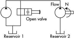
Another way to look at this scenario is with a hydraulic analogy (Fig. 8). The circuit has two different reservoirs that aren’t interconnected. As long as the two-port valve is positioned as shown, fluid is pumped around the first circuit. However, when the valve is closed, the fluid will soon transfer to the motor and end up in reservoir #2. Clearly, this will not work.
If we fail to connect the common terminals in the electrical circuit, the consequence is more subtle, but the result is a very noisy (electronically speaking, not necessarily audible) operation, and machine axes can drift, jitter, jump around, or simply not function. In the hydraulic system, all reservoirs need to be interconnected, as do the common terminals on all electronic gadgets.
